


2
Tools and Supplies
Recommended tools include pliers and a athead screwdriver. If you need to
route the module connector through a bulkhead, you will need a drill and a 7/8”
(22 mm) drill bit. If you are mounting the module directly to at, horizontal
surface, you will need a #31 (3 mm) drill bit for the screw holes.
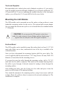
Mounting the LGC Module
The GPS module can be mounted on any at surface as long as there is room
behind the mounting surface for the screws. The optional pole mount adapter
lets you mount the antenna on a pole or swivel mount that uses standard marine
1”-14 threads.
Surface Mount
The GPS module can be installed on any at surface that is at least 3-1/2” (90
mm) wide. Make sure a clear, unobstructed view of the sky is available at the
selected location.
Once you have determined the mounting location, drill the screw holes. The
screws supplied with this unit are about 1-1/8” long (4 mm x 30 mm). Drill .120
diameter (3 mm) holes for the mounting screws.
If you need to route the cable through the mounting surface, drill a 7/8” (22
mm) hole for the cable’s connector. The notch in the antenna housing allows
the cable to pass through, if desired, instead of routing it down through the
mounting surface.
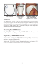
After drilling the holes, pass the O-ring over the cable and press it into the
groove on the bottom of the antenna housing.
Now attach the antenna to the mounting surface, using 4 mm screws and lock
washers. Route the cable to where it connects to the network and plug it in. The
installation is complete.
CAUTION: Do not mount the GPS module in the direct
path of a radar antenna’s beam. Radar radiates high-energy
signals that can interfere with GPS signal reception.
!