


| 13
Display Installation | HDS Gen2 Touch Installation Manual
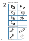
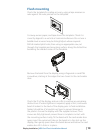
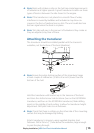
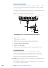
Flush mounting
Check the template for scaling accuracy, using a tape measure or
ruler against the ruler printed on the template.
MOUNTING SCREW SIZE IS #6 TAPPING SCREW
L
C
L
C
Check dimensions before cutting
12"
SUN COVER
PRODUCT OUTLINE
199.0 mm (7.83")
190.5 mm (7.50")
220.4 mm (8.68")
95.3 mm (7.50")
99.5 mm (3.92")
95.3 mm (7.50")
110.2 mm (3.75")
Cut away excess paper, and tape down the template. Check it is
correctly aligned to a vertical or horizontal reference. Do not use a
bubble level as vessel may be listing! Adjust where required.
Drill all marked pilot holes, then using an appropriate saw, cut
through the template and mounting surface, along the dotted line
bordering the shaded center of the template.
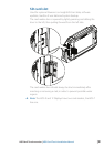
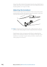
Remove the bezel from the display, using a ngernail or small at
screwdriver, starting at the edges that are closest to the card reader
door.
Check the t of the display, and use a le to remove any remaining
obstructions. If water-tightness is required, apply a thin, continuous
bead of sealant to the back of the display prior to nal installation.
Sealant should be of a ‘neutral cure’ type to prevent damage to
the plastics. Secure the display with the supplied screws. Once
screws are fully tightened, ensure there is complete contact with
the mounting surface. Lastly, t the bezel with the card reader door
open; insert the outermost tabs on the bezel in to the slots on the
display, then gently press down the bezel above and below the card
reader door till it clicks in to place.