


20 |
Wiring | HDS Gen2 Touch Installation Manual
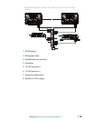
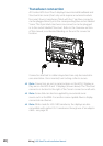
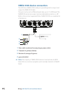
Transducer connection
All Combo HDS Gen2 Touch displays have internal Broadband and
StructureScan sonar (chart only units require an external module
for sonar). Navico transducers tted with the 7 pin blue connector
can be plugged directly into the corresponding blue socket labeled
‘Sonar’. The 9 pin black structure scan connector can be plugged
in to the socket labelled ‘Structure’ . Refer to the Overview section
of this manual, or embossed labeling on the unit for connector
location.
Connector attached to cable is keyed and can only be inserted in
one orientation. Once inserted, turn locking collar to secure.
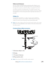
¼ Note: Connectors are not in same location on the HDS-7 display as
they are on the HDS-9 and 12 displays (shown above). The ‘Structure’
connector is located to the right of the ‘Sonar’ connector on all units.
¼ Note: Sonar data can also be supplied by an external sonar
source such as the BSM-2 or another sonar capable Navico display
connected via ethernet.
¼ Note: While made for LSS-2 HD transducer, the displays are also
compatible with earlier LSS-1 transducers through use of an adaptor
cable - see page 30.