


2
INSTALLATION
Before installing the keypad, the unit must be partially
disassembled to access the mounting plate. The keypad’s bezel
can be exchanged for a different color when the keypad is apart.
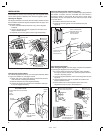
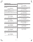
Opening the Keypad
The keypad assembly is secured with two tamper-resistant screws
that are hidden behind the keypad’s faceplate. Refer to Figure 3 for
disassembly details.
❑ Use a small fl at blade screwdriver to pry off the keypad’s
faceplate.
❑ Use the special allen wrench (supplied) to remove the two
tamper-resistant screws.
❑ Separate the mounting plate from the keypad assembly.
Changing the Keypad’s Bezel
The colored keypad bezels snap onto the keypad assembly. Refer
to Figure 4 for details on changing the bezel.
❑ Gently pull on the edge of the bezel to release the tabs that
hold the bezel to the keypad assembly.
❑ Remove the bezel from the keypad assembly.
❑ Choose the proper color bezel for the installation and snap
it onto the keypad assembly.
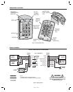
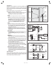
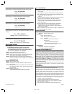
Install the Electrical Box and Mounting Plate
The keypad is designed to fi t into a standard single-gang electrical
box. Select a location near the controlled door and choose a
convenient height for the keypad. Be sure there is good wiring
accessibility for the unit’s power and the output to the door strike
or access device.
❑ Install the electrical box in the wall.
❑ Screw the mounting plate onto the electrical box (see
Figure 5).
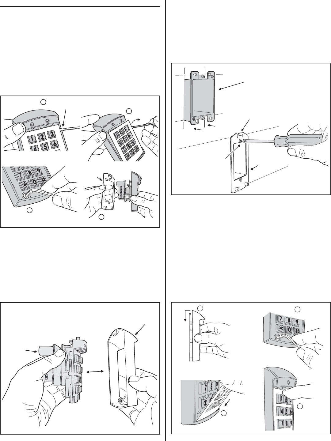
Final Keypad Installation
After wiring the keypad (see next page), complete the installation
by securing the keypad to the mounting plate.
❑ If a lower beeper sound level is required, before installing
the keypad, remove Jumper JP1 (place the jumper block on
one pin to save the jumper).
❑ Hook the keypad assembly onto the mounting plate tab (see
Figure 6).
❑ Use the special allen wrench (supplied) to install the two
tamper-resistant screws.
❑ Fit the bottom tab on the faceplate into the slot on the
keypad then snap the top of the faceplate in.
HOOK THE KEYPAD ASSEMBLY
ONTO THE MOUNTING PLATE
1
2
3
4
INSTALL THE
TWO SCREWS
FIT THE BOTTOM TAB OF
THE FACEPLATE INTO THE
SLOT ON THE KEYPAD
SNAP THE TOP
OF THE KEYPAD
INTO PLACE
Figure 6. Connecting the Keypad to the Mounting Plate
228045 A IMAGE 4
PRY UP ON THE
FACEPLATE HERE
1
2
3
4
REMOVE THE
FACEPLATE
REMOVE THE
TWO SCREWS
SEPARATE THE
MOUNTING PLATE
FROM THE KEYPAD
MOUNTING
PLATE
Figure 3. Opening the Keypad
KEYPAD
BEZEL
·
SATIN-CHROME (FACTORY INSTALLED)
·
WHITE
·
IVORY
·
BRONZE
KEYPAD BEZEL COLORS:
THE BEZEL SNAPS
ONTO THE KEYPAD
ASSEMBLY
KEYPAD
ASSEMBLY
Figure 4. Changing the Outer Bezel
INSTALL A SINGLE-GANG
ELECTRICAL BOX AT THE
PROPER LOCATION
FOR THE KEYPAD
ATTACH THE MOUNTING
PLATE TO THE
ELECTRICAL BOX
MAKE SURE THE
TAB IS UP
MOUNTING
PLATE
Figure 5. Installing the Mounting Plate