2
Manual No. 701-094M 11/23/05
Land Pride
Assembly Instructions
■
Air Intake Installation
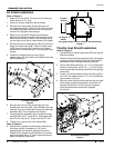
Refer to Figure 3:
1. Refer to air hose (#1A). Cut one end of existing air
intake hose to 4 1/4" long.
1. Orient air diverter assembly (#5) as shown.
2. Slip two worm drive hose clamps (#9) over the
air intake hose (#1A). Insert air hose (#1A) over the
air intake nozzle (#8) and over the air diverter (#5)
nozzle. Do not tighten hose clamps.
3. Refer to air hose (#1B). Measure the distance
between the diverter assembly (#5) nozzle to the air
filter inlet nozzle (#10). Add 2" to this distance and
cut the other end of the air intake hose to this length.
4. Slip two worm drive hose clamps (#9) over the cut to
length air intake hose (#1B). Insert air intake hose
(#1B) over air diverter (#5) nozzle and air intake
nozzle of air filter canister (#12). Do not tighten hose
clamps.
5. Expand the flexible heat riser tube (#3) to
approximately 30". Be careful not to deform the tube
while expanding it.
Air Intake Installation
Figure 3
6. Slip two worm drive hose clamps (#9) over the
flexible heat riser tube (#3). Insert flexible heat riser
tube (#3) over air diverter (#5) nozzle and heat tube
weldment (#2). Do not tighten hose clamps.
7. Clamp heat tube weldment (#2) to engine exhaust
manifold (#4) with 2" U-bolt (#14), clamp plate (#6)
and 3/8" hex nuts (#13). Torque nuts to 20 ft. lbs.
8. Tighten all six worm drive hose clamps (#9).
Refer to Figure 4:
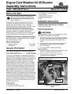
9. Rotate the air bypass handle counter clockwise to
the winter position marked with a “W” when
temperatures are below 45 degrees Fahrenheit.
Rotate the air bypass handle clockwise to summer
position marked with a “S” when temperatures are
above 45 degrees Fahrenheit.
22441
Air Bypass Handle
Air Bypass handle Position (Summer Position Shown)
Figure 4
Throttle Heat Shield Installation
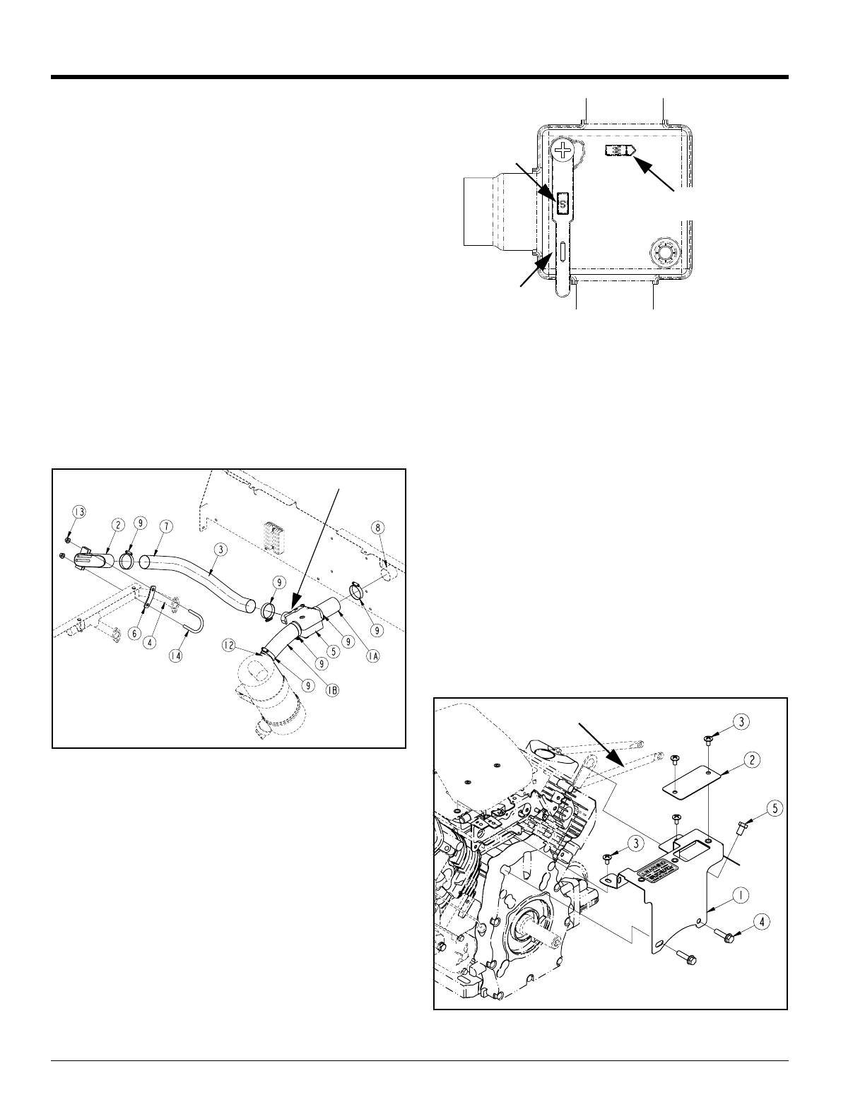
Refer to Figure 5:
1. Remove M8 hex flange cap screw (#5) from engine
stabilizer bracket.
1. Position heat shieldcover assembly (#1)onto engine
housing as shown. Make certain the heat shield is
positioned under the engine stabilizer bracket.
2. Secure heat shield with two 1/4" x 1/2" phillips head
machine screws (#3), two 5/16" x 1 1/4" hex flange
head screws (#4) and replace the M8 hex flange cap
screw (#5).
3. Torque 1/4" phillips heads machine screws to 5.6 ft.
lbs, 5/16" hex head screws to 17 ft. lbs. and M8 hex
cap screws to 19 ft. lbs.
4. Warm air cover (#2) should be secured over the heat
shield opening when temperatures are below 45
degrees Fahrenheit and over the warning decal
when temperatures are above 45 degrees
Fahrenheit.
Heat Shield Installation
Figure 5
Winter
Position
Summer
Position
Air Bypass
Handle
22451
Stabilizer
Bracket