


2
|
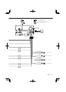
DNX9140//DDX814/DDX8034BT
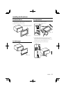
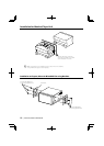
Installation Procedure
1
..........1
2
..........1
3
..........1
4
..........1
5
..........2
6
..........1
7
..........1
8
..........6
9
..........6
0
..........1
!
DNX9140 only
..........1
@
DNX9140 only
..........1
#
..........1
$
DNX9140 only
..........1
%
DNX9140 only
..........1
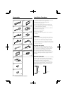
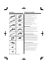
Accessories
1. To prevent a short circuit, remove the key from the
ignition and disconnect the - battery.
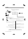
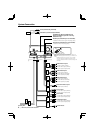
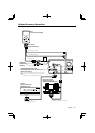
2. Make the proper input and output wire
connections for each unit.
3. Connect the speaker wires of the wiring harness.
4. Connect the wiring harness wires in the following
order: ground, battery, ignition.
5. Connect the wiring harness connector to the unit.
6. Install the unit in your car.
7. Reconnect the - battery.
8. Press the reset button.
9. Perform the Initial Setup. (Refer to the Instruction
Manual.)
2WARNING
• If you connect the ignition wire (red) and the battery wire
(yellow) to the car chassis (ground), you may cause a short
circuit, that in turn may start a fire. Always connect those
wires to the power source running through the fuse box.
• Do not cut out the fuse from the ignition wire (red) and the
battery wire (yellow). The power supply must be connected
to the wires via the fuse.
Acquiring GPS Signals
The first time you turn on DNX9140, you must wait
while the system acquires satellite signals for the first
time. This process could take up to several minutes.
Make sure your vehicle is outdoors in an open
area away from tall buildings and trees for fastest
acquisition. After the system acquires satellites for the
first time, it will acquire satellites quickly each time
thereafter.
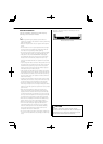
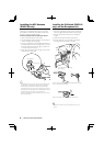
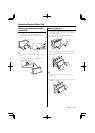
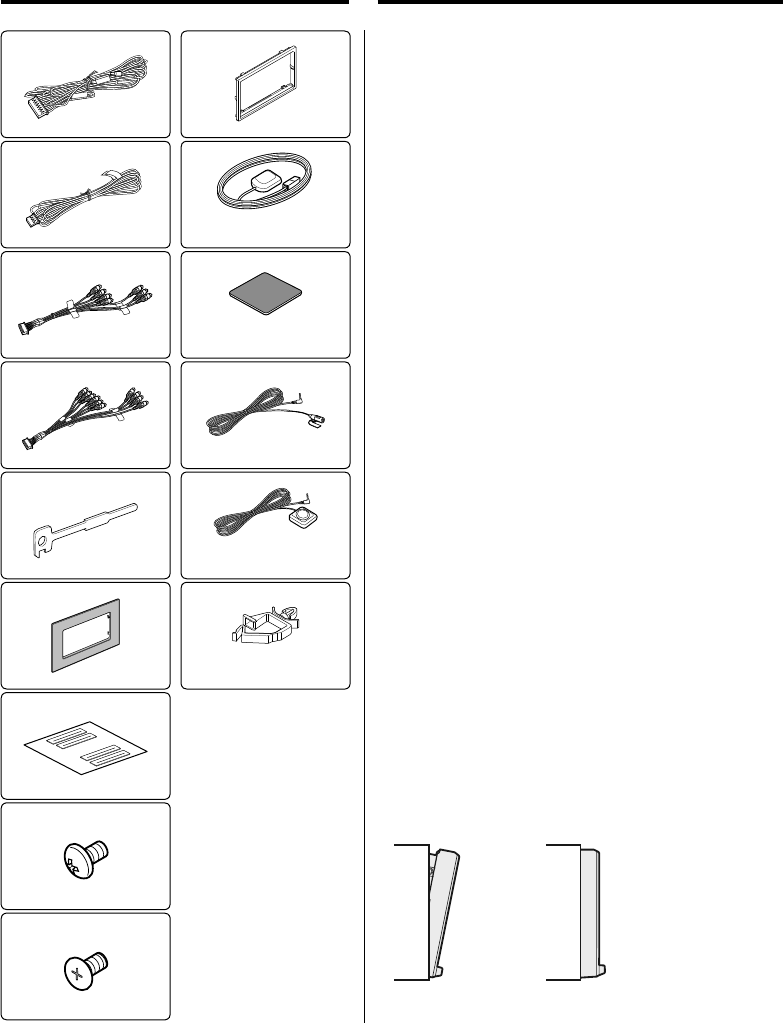
About the Front Panel
When removing the product from the box or installing
it, the front panel may be positioned at the angle
shown in (Fig. 1). This is due to the characteristics of a
mechanism the product is equipped with.
If the program that is activated when the product is
first powered on works properly, the front panel will
automatically move into the position (initial setting
angle) shown in (Fig. 2).
(Fig. 1)
(Fig. 2)