


•
Route the wires down from the rearside of the tachometer
housing through the upper fork clamp wire and hose guide and
into the rear of the headlight shell.
•
Connect the black and red tachometer wires inside the headlight
housing as indicated in the schematic below.
•
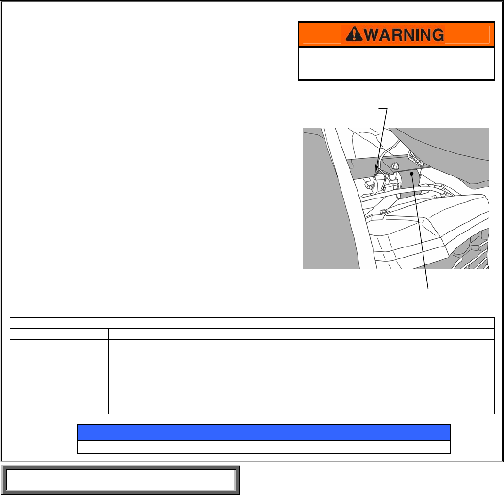
Locate the left coil just under the front of the fuel tank. Remove
the black/orange wire connector from the left coil and install the
green piggyback spade connector from the tachometer onto the
coil and reinstall the black coil wire onto the piggyback
connector’s male spade terminal. Secure the wire with the
supplied cable tie to existing harnesses.
• Reconnect the 3-pin headlight plug onto the back of the headlight
and reinstall the headlight assembly onto the headlight shell,
making sure to hook the top edge first and firmly snapping the
bottom edge closed. Align the mounting holes and re-secure the
headlight ring with the two cross-point screws.
•
Start the engine and check the operation and lighting of the
tachometer.
Be sure the ignition to the motorcycle is
turned off prior to making any electrical
connections
NOTICE
Care and Cleaning: Do not use abrasive cleaners; wash with mild soap and warm water.
Please check / adjust all screws in regular intervals.
Kawasaki Motors Corp. U.S.A., Jun 2009
WIRE SCHEMATIC FOR VN1700 TACHOMETER
Tachometer Wires: Motorcycle Wires: Notes:
Red Yellow (accessory power) Insert male bullet connector into double female
bullet connector inside headlight shell.
Black Black / Yellow Stripe (accessory
ground)
Insert male bullet connector into double female
bullet connector inside headlight shell
Green Black / Orange Stripe Coil Wire Green spade piggyback connector on to pin on coil
where stock black wire was installed, reinstall black
wire on to piggyback connector on coil
BLACK/ORANGE
COIL WIRE
LEFT IGNITION
COIL
GAS TANK