


2-18 SERVICE DATA
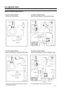
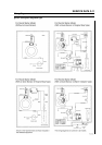
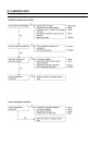
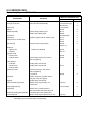
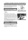
Disassembly Sequence (FE120, 170)
Bolt to be removed for tool
Disassembly Precaution
Name Quantity
Drain Plug Warm up engine and drain oil. 14 across flats
Fuel Tap, Fuel Tank Drain fuel before disassembly. 17 across flats (tap) 1
M6 bolt (tank) 4
Spark Plug 21 across flats
Shroud M6 bolt 6
Muffler Assembly Remove flange retaining nuts. M6 nut 2
Remove stay retaining bolt. M8 bolt 1
Air Cleaner M5 butterfly bolt 2
Carburetor Tighten it together with air cleaner case. M6 nut 2
Governor Arm, Control Panel M6 nut 1
M6 bolt 2
Fan Housing Disconnect wire to stop switch. M6 bolt 5
(FE120 = 4)
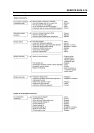
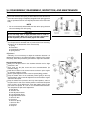
Electrical:
• Ignition Coil * FE120 uses M6 bolts. M5 bolt 2
• Flywheel M14 nut 1
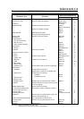
Cylinder Head:
• Rocker Case M6 bolt 4
• Cylinder Head Loosen boltss evenly in the reverse M8 bolt 4
order of tightening.
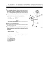
Valve System:
• Pushrods Identify intake and exhaust.
• Rocker Arms Identify intake and exhaust. M6 nut 2
• Exhaust Valve
Crankcase Cover Loosen bolt evenly in the reverse
order of tightening.
for FE120 M6 bolt 8
for FE170 M8 bolt 7
Camshaft Remove shaft from a position where
cam gear marks are aligned.
Tappets Identify intake and exhaust.
Governor Shaft (Arm Pivot) Remove snap ring and pull it out Snap ring 2
of crankcase.
Connecting Rod Cap 10 across (bolt) 2
Crankshaft Remove from a position where it
does not interfere with connecting rod.
Piston/Connecting Rod Assembly Pull it downward from cylinder bore.
Connecting Rod Remove snap ring and pull piston pin out. Snap ring 2
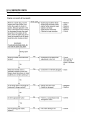
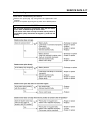
Assembly sequence (for FE120, 17):
Assembly parts in the reverse order of disassembly.