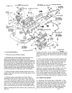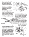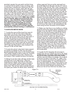
9.1 Locate the rubber sleeves and the front cross
over pipe. Check inside the cross over pipe for
debris and clean it out if necessary. Install the cross
over tube between the idle air manifold (dummy
throttle body now on the intake manifold) and the
supercharger manifold. If you find the outlet rubber
sleeves hard to slip over their respective landings,
use some spray light oil such as WD40 which dries
off to lubricate the situation. Do not use gasoline
products or pure silicone products. The best tech-
nique for installing the cross over tube involves put-
ting the 2.75” diameter rubber sleeve on the super-
charger manifold and the 2.5” diameter sleeve on
the cross over tube, and attach both with clamps.
Then install the cross over tube, starting at the
supercharger end first. Note that the cross over pipe
goes over the radiator hose.
9.2 Once the cross over pipe is installed correctly,
double-check all your hose and tube connections.
There should be no loose ends or connections. Do
not overtighten any hose clamps, but eisure that
they are snug. Double check your power steering
belt and supercharger belt for correct tension.
9.3 You are now ready to start your engine.
9.4 CLEARANCES
IMPORTANT! MAKE SURE THAT YOU HAVE AT
LEAST 3/4” INCH CLEARANCE BETWEEN ANY
ENGINE MOUNTED COMPONENT AND ANY
BODY MOUNTED COMPONENT. CRITICAL
AREAS:
• BYPASS ACTUATOR TO BRAKE LINES (VERY
CRITICAL - The engine “rocks” strongly to the dri-
ver’s side upon deceleration. If clearance is too
tight, your brake lines can be gently deformed
away from the supercharger bypass actuator by
hand.)
• SUPERCHARGER OUTLET MANIFOLD TO AIR
FILTER (INCLUDING CLAMPS)
• ALL VACUUM LINES TO THROTTLE SPOOL &
CABLE
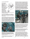
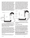
9.5 SUPERCHARGER BELT DRIVE ADJUSTMENT
Start your engine and observe your belt drive. The
belt should line up with itself as it passes between
the two aluminum idlers. To put it a different way,
the portion of the belt running up to the super-
charger should lay directly over the portion leaving
the supercharger and heading toward the power
steering pulley. If the upward run is more forward or
rearward than the downward run, you need to
move your supercharger slightly forward or back-
ward with respect to the crankshaft pulley.
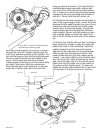
Remember the two bolts attaching the supercharg-
ers bracket to the cylinder head from step 6.1? You
can now access these two bolts with an open-end
wrench. Loosen each bolt slightly to allow for
adjustment. Start the engine. You can now move
the supercharger assembly slightly forward or rear-
ward to correctly align the drive pulleys. The slots
in the supercharger mounting bracket will allow
you to find the perfect alignment for the belt run.
NOTE: Do not attempt to move the supercharg-
er with your hands with the engine running.
Use an appropriate tool. The best tool to use is a
flat blade screwdriver placed between the forward
bracket bolt and the front inside edge of the brack-
et. Move the supercharger assembly while watch-
ing the belt run the idler pulley. If you have the two
bracket bolts too loose, the supercharger will be
out of alignment from side to side. Make sure the
two bolts are snug enough to just allow some
leveraged movement. Once you have the belt run-
ning true in the center of the idler pulleys, tighten
the rear bolt to secure the position. Shut off the
engine and tighten the other bracket bolt securely.
Recheck all mounting bolts for tightness.
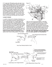
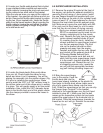
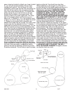
9.6. For trouble shooting and testing prior to driving
your newly supercharged Miata follow these proce-
dures. Unscrew the back of the “Jackson Racing
PowerCard” box. You will see 3 LED lights in a
row. The Yellow, Red and Green lights are fuel
enrichment lights and MIL (Malfunction Indicator
Lights) lights. Read the lights and refer to the fol-
lowing table to find the source of the MIL problem.
If the box has been wired for power and ground
correctly you will see the Green light is illuminated
and flashing with the ignition switch in the “On”
position and the engine off. Start the car and check
that the Green light is illuminated continuously and
not flashing. There should be no other lights illumi-
nated. If you have no lights when you power up
the vehicle, you either have a power (Red wire) or
ground (Black wire) problem. Double-check your
connections at these two wires until they test prop-
erly.
If the Green light is flashing after the vehicle is
started, the Blue wire is not connected to an injec-
tor wire or the connection is not complete. If the
yellow light is flashing one of the Gray wires has a
bad connection or is not connected to an injector
wire. The Yellow MIL light will not function if the
Green light is also flashing. In this case you must
fix the Blue wire problem first.
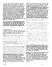
Inside the box is one more LED located away from
the other three LED’s. This is your “Boost
Activation” LED. Once the engine is warmed up,
push the throttle hard so that the engine gains
RPM quickly (creates Boost) and then let it come
back to idle. During this process this LED should
become illuminated temporarily. It only comes on
when the Pressure Transducer in the box reads
boost from the
engine.
12
1/07999-200


