


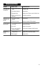


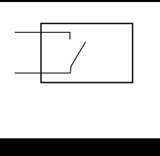
Reed Relay Specifications
•Two wire SPST N/O.
•Switching voltage 150 VDC; maximum
current 0.25 Amps.
•Rating 3 watts.
•Duty cycle 20% ON, 80% OFF.
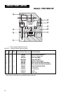
Disassembly:
1. Ensure the fluid supply to the meter has
been disconnected, and the line pres-
sure has been released before disas-
sembly.
2. Remove the four screws and remove the
pulser cap.
3. Remove the gasket.
4. Remove eight screws and remove the
meter cap.
5. Remove O-ring and inspect. Replace O-
ring if damaged.
6. Remove rotors, clean and inspect. Re-
place rotors if damaged.
7. To remove the PCB, remove the two
screws.
NOTE: Reed Switch PCB’s cannot be re-
moved.
2
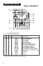
Reassembly:
1. Replace rotors into the meter body. The
rotors should be at 90 degrees to each
other.
2. Lightly rotate the rotors by hand. They
must rotate freely.
3. Install O-ring.
4. Replace the meter cap and tighten the
eight screws uniformly to 35Nm (25 Ft.
Lbs.).
5. Replace the pulser cap and tighten the
four screws.
MAINTENANCE
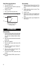
Figure 3
12
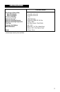
Reed Switch Wiring Details
(HP Models Only)