


OPERATING INSTRUCTIONS
PAGE 3 OF 8
651615-X
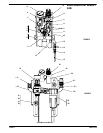
LIFT/RAM INSTALLATION
WARNING Failure to properly install the lift assembly can
result in severe personal injury and property damage. Read
the warning on page 2.
1. Establish the desired location for the lift/ram and pay special attenĆ
tion to work area above, this area above the lift must be open, withĆ
out obstructions and safely away from any electrical devices.
2. Place the pump on the follower plate and align the pump and folĆ
lower plate onthe baseand assemblepump tothe mountingbrackĆ
et on the ram.
3. Assemble air hose to air motor inlet.
4. Install the check and follower plate air hose from the Control Valve.
5. Assemble the vent plug to the follower plate.
NOTE: The ram was tested at the factory. The unit should be generally
checked over for leakage because the fittings on the system may have
loosened in shipment.
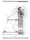
OPERATING INSTRUCTIONS / INITIAL SETUP PROCEDURE
WARNING STAND CLEAR. When raising or lowering the
lift. Read the warning on page 2.
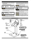
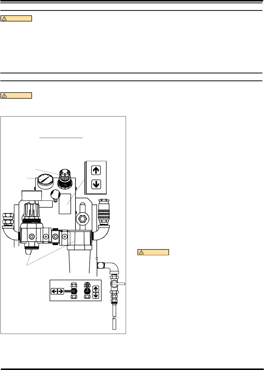
PRESSURE
REGULATOR
FOLLOWER PLATE
AIR SUPPLY VALVE
CONTROL
LEVER
GAUGE
AIR CONTROLS
FIGURE 2
OFF
ON
UP
NEUTRAL
DOWN
PUMP
FILTER-REGULATOR
TO RAISE LIFT, (THE FIRST TIME):
1. Take note of the pump/drum clearance above. Be certain the lift is
clear of any objects above. Also refer to OPERATING AND SAFEĆ
TY PRECAUTIONS found on page 2.
2. Connect the air supply (160 PSI MAX) to the air inlet.
3. Shift the control valve lever to the ``UP'' position.
4. Raise the lift high enough to clear the height of the drum. Stop the
lift upward travel by moving the control valve lever to the (center)
``NEUTRAL'' position.
TO RAISE LIFT, (NORMAL OPERATION):
1. Adjust the Follower Plate Air Valve pressure up to approximately 8
psig. DO NO OVERPRESSURIZE THE DRUM to avoid damage.
NOTE: Air from this valve will only pass when the Control Lever is
in the ``UP'' position.
2. Shift the control valve lever to the ``UP'' position.
3. Raise the lift high enough to clear the height of the drum. Stop the
lift upward travel by moving the control valve lever to the (center)
``NEUTRAL'' position.
TO CHANGE DRUM:
NOTE: The Control Lever should be in the ``NEUTRAL'' position.
1. Place a new drum into position.
TO LOWER LIFT:
WARNING
PINCH HAZARD. Follower can descend quickly
causing injury. Keep hands clear when aligning with containĆ
er. Read the warning on page 2.
NOTE: Be certain the Follower Plate vent plug has been removed so
that the air trapped between the follower and the material is allowed to
escape from this vent. Captured air between the follower plate and
drum will escape.
NOTE: The lift may hesitate momentarily before starting downward,
the air pressure insidethe post air chamber mustdecrease before it will
begin to descend.
1. Shift the control valve leverto the``DOWN''position andproceed to
lower the pump.
2. Replace the vent plug once the material begins to ooze from the
vent opening.