


650891-X-B
PUMP OPTION DESCRIPTION CHART
650891- X
PACKING MATERIAL
PLUNGER TYPE
SPRING ARRANGEMENT
PACKING MATERIAL (PACKINGSARE UPPERANDLOWERUNLESS NOTED)
3 Glass Filled PTFE P UHMW- PE / PTFE Stag’d (Upper)
C UHMW-PE UHMW-PE (Lower)
G UHMW-PE / Leather Staggered R PTFE / UHMW-PE Stag’d (Upper)
Glass Filled PTFE (Lower)
SPRING ARRANGEMENT
PLUNGER TYPE
4 Multiple Wave Spring 7 HD SS W / HD Chrome Plating
47-B
GENERAL DESCRIPTION
WARNING
HAZARDOUS PRESSURE. Do not exceed maxi-
mum operating pressure of 5964 p.s.i. (411.3 bar) at 120 p.s.i.
(8.3 bar) inlet air pressure.
PUMP RATIO X
INLET PRESSURE TO PUMP MOTOR
=
MAXIMUM PUMP
FLUID PRESSURE
Pump ratio is anexpression of therelationship betweenthe pump motorarea andthe
lowerpumpendarea.EXAMPLE:When120p.s.i.(8.3bar)inletpressureissuppliedto
themotorofa4:1ratiopumpitwilldevelopamaximumof480p.s.i.(33.1bar)fluidpres-
sure(atno flow) --asthe fluidcontrolis opened,theflowratewillincreaseasthemotor
cycle rate increases to keep up with the demand.
WARNING
Refer to general information sheet for additional
safety precautions and important information.
• The Chop -Check pumps areprimarily designed for the pumpingof
heavy viscous material with or without fibrous content. The models
can be used with a gravity feed single post lift as a topper type as-
semblyor witha twopostlift asa forcefeed typeassembly.The low-
er pump is designed for easy priming and the double acting feature
is standard i n all ARO industrial pumps. Material is delivered to the
pump discharge outlet on both the up and down stroke.
• The motor is connected to the lower pump end by a spacersection.
This allows for lubrication of the upper packing gland and prevents
motorcontamination becauseof normalwearand eventualleakage
through the material packing gland. Be sure the solvent cup is ade-
quately filledwith lubricantto protect the upperpackings and insure
longest service life.
TROUBLE SHOOTING
Pump problems can occur in either the Air Motor Section or the Lower
Pump EndSection. Use these basicguidelines to help determinewhich
section is affected.
If the pump will not cycle.
• Becertaintofirst checkfornon-pumpproblemsincludingkinked,re-
strictive or plugged inlet /outlet hose or dispensing device. Depres-
surize the pump system and clean out any obstructions in the inlet /
outlet material lines.
• Refer to the motor manual for trouble shootingif the pump does not
cycle and / or air leaks from the air motor.
If the pump cycles but does not deliver material.
• Refer to the lower pump end manual for further trouble shooting.
PUMP CONNECTION -- UPPER / LOWER
NOTE: All threads are right hand.
1. Lay the pump assembly on a workbench.
2. Remove the three nuts from the three spacer rods (figure 1).
3. Pulltheair motorfromthelower pumpend untilmotorpistonrod isin
the ‘‘down” position and lower pump end rod is in ‘‘up” position.
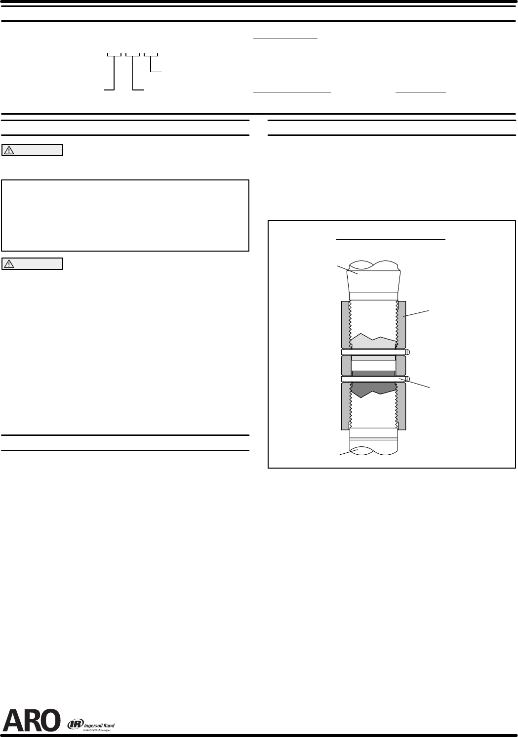
4. Removethecotterpinsandunthreadpistonrodsfromtheconnector
(figure 2).
Lower Pump
Piston Rod
Pump Motor
Piston Rod
CONNECTOR
92226
COTTER PIN
Y15-46-C (2)
PUMP CONNECTOR DETAIL
FIGURE 2
REASSEMBLY
1. Threadtheconnectortothepumpmotorpistonroduntiltheholethru
the connector is aligned with the hole thru the piston rod.
2. Assemble the cotter pin thru the hole and bend the ends of the pin
into the groove of the connector.
3. Threadtheconnectorto thelowerpumppistonrod untiltheholethru
the connector is aligned with the hole thru the piston rod.
4. Assemble the cotter pin thru the hole and bend the ends of the pin
into the groove of the connector.
5. Note: Heads and ends of cotter pins must not extend more than
.125” beyond o.d. of connector.
6. Reinstall the spacer rods to the pump motor.
7. Bring the motor and lower pump together and retain with the three
nuts.
PN 97999-834