


Page 4 of 8 650718-C (en)
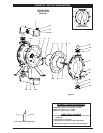
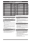
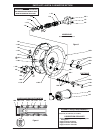
PARTS LIST / 650718-C FLUID SECTION
n
637138-63 uid section service kits include: Balls (item 22), diaphragms (item 7) plus items 2, 3, 19 and 93706-1 Key-Lube grease
(page 6).
MATERIAL CODE
[A] = Aluminum
[B] = Nitrile
[Br] = Brass
[C] = Carbon Steel
[Co] = Copper
[D] = Acetal
[K] = Kynar PVDF
[SS] = Stainless Steel
[V] = Viton
Service Note: Part number 98931-T installation tool is available separately for use with items (1) and (2).
o
“Smart Parts”, keep these items on hand in addition to the service kit for fast repair and reduction of down time.
p
Service Kit Note: Extra “O” rings are included in kits to service models built prior to December 1989.
PARTS LIST
Item Description
(size)
Qty Part No. [Mtl]
o
1 Rod (1) 98720-1 [C]
n
2 “O” Ring
(3/32” x 1” o.d.)
(1) Y330-117 [B]
n
3 “O” Ring
(1/16” x 3/4” o.d.)
(4) Y327-16 [V]
5 Plate - air side (2) 92752 [C]
o
6 Plate - uid side (2) 92752 [C]
n
7 Diaphragm (2) 92755-3 [V]
9 Washer
(0.630” i.d.)
(2) 93065 [SS]
14 Screw
(5/8” - 18 x 1-1/2”)
(2) Y5-107-T [SS]
15 Fluid Cap (2) 92750 [A]
16
Manifold
(top with valve port)
(1) 93128 [A]
Manifold
(bottom)
(1) 92749 [A]
Item Description
(size)
Qty Part No. [Mtl]
n
19 “O” Ring
(1/8” x 2-3/4” o.d.)
(4) Y327-230 [V]
21 Seat (4) 92942 [K]
n
22 Ball
(1-3/4” diameter)
(4) 92757-6 [D]
26 Bolt
(3/8” - 16 x 1-1/4”)
(8) Y6-66-C [C]
27 Bolt
(5/16" - 18 x 2-1/4”)
(4) Y6-510-C [C]
29 Nut
(5/16" - 18)
(20) Y12-5-C [C]
32 Leg (2) 92759 [C]
43 Ground Lug
(see page 7)
(1) 93004 [Co]
59 Bolt
(5/16" - 18 x 2”)
(16) 93608 [C]
81 Relief Valve (1) 96333 [Br]
FLUID SECTION DISASSEMBLY
Remove top manifold(s).
Remove (22) balls, (19) “O” rings and (21) seats.
Remove (15) uid caps.
Remove (14) screw, (9) washer, (3) “O” ring, (6) plate, (7)
diaphragm and (5) plate.
Remove (3) “O” rings.
NOTE: Do not scratch or mar the surface of (1) diaphragm
rod.
1.
2.
3.
4.
5
.
FLUID SECTION REASSEMBLY
Reassemble in reverse order.
Clean and inspect all parts. Replace worn or damaged
parts with new parts as required.
Lubricate (1) diaphragm rod and (2) “O” ring with Key-
Lube “O” ring lube or equivalent.
Use ARO pn 98931-T bullet (installation tool) to aid in in-
stallation of (2) “O” ring on (1) diaphragm rod.
Be certain (7) diaphragms align properly with (15) fluid
caps before making nal torque adjustments on bolt and
nuts to avoid twisting the diaphragm.
Re-check torque settings after pump has been re-started
and run a while.
y
y
y
y
y
y