


AIR AND LUBE REQUIREMENTS
WARNING
S The air supply line or hose to the pump should be adequately sized
to carry a sufficient volume of air to the pump. The material inlet supĆ
ply tubing should not be too small or restrictive which will inhibit maĆ
terial flow. The outlet material volume is governed not only by the air
supply but also by the material volume available at the inlet.
S Air supply provided should be filtered to provide clean dry air. A filter
capable of filtering out particles larger than 50 microns should be
used on the air supply. There is no lubrication required other than the
O" ring lubricant which is applied during assembly or repair.
S If lubricated air is present, make sure that it is compatible with the
Nitrile O" rings in the air motor section of the pump.
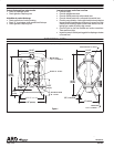
INSTALLATION
S Requirements for the installation are included in the Flammable and
Combustible Liquids Code, NFPA No. 30, Automotive and Marine
Service Station Code, NFPA No. 30A and the National Electric
Code, ANSI / NFPA No. 70.
S A fluid return hose which is compatible with the fluid being pumped
must be installed to the relief valve on the outlet manifold to return
fluid back to the supply tank or pump inlet.
S The pump must be grounded to prevent static discharge. Grounding
may be accomplished through the legs or to the ground lug provided
on the pump.
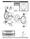
S Notice that the material inlet / outlet manifolds may be removed and
rotated 180_ to facilitate various mounting applications.
S If the body of the pump must be rotated, remove the end covers and
manifolds and index it so the bolts line up properly. NOTE: The arrow
on the end caps must always point upward for optimum perforĆ
mance.
S When the diaphragm pump is used in a forceĆfeed situation, it is recĆ
ommended that a check valve be installed at the air inlet to keep maĆ
terial out of air line in the event of diaphragm failure.
S Secure diaphragm pump legs to a suitable surface to insure against
damage by excessive vibration.
OPERATING INSTRUCTIONS
S
The pump should never be operated at pressures exceeding 50
p.s.i.g. (345 kPa) inlet air pressure. This pump is equipped with a
pressure relief valve on the material outlet manifold which will open
at 40 +/Ć4 p.s.i. (2.76 bar) to relieve pressure increases in the outlet
hoses / plumbing caused by thermal expansion or other external
forces.
S Disconnect the air supply from the pump if it is to be inactive for a few
hours.
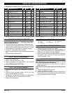
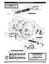
MAINTENANCE
Refer to the part views and descriptions as provided on page 4 through 7
for parts identification and Service Kit information.
S Certain ARO Smart Parts" are indicated which should be available
for fast repair and reduction of down time.
S Service kits are divided to service two separate diaphragm pump
functions: 1. AIR SECTION, 2. FLUID SECTION. The FLUID SECĆ
TION is divided further to match typical part MATERIAL OPTIONS.
S Provide a clean work surface to protect sensitive internal moving
parts from contamination from dirt and foreign matter during service
disassembly and reassembly.
S Keep good records of service activity and include pump in prevenĆ
tive maintenance program.
S Before disassembling, empty captured material in the outlet manĆ
ifold by turning the pump upside down to drain material from the
pump.
S KynarR is a trademark of Penwalt Corp, S KeyĆLubeR is a trademark of Key Industries.