


HQ-006 I&M Manual HQ-402-0606 5
6.0 Electrical Connection
Move valve to mid-position by override nut. This will allow sufficient time to stop actuator in case of
improper hook-up
Identify means of removing power during hook-up
Be sure no erroneous remote control signals can be received causing actuator to energize
Electrically operate the valve in the open direction. If the valve closes, actuator must be stopped and
checked for improper field wiring
Set all field conduit entries in accordance with National Electric Code Requirements
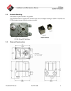
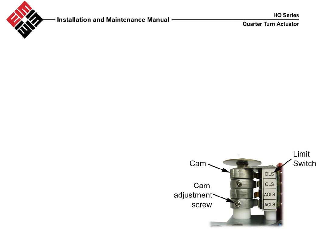
7.0 Limit Switch Setting Instructions
• Operate the actuator manually to closed
position
• Using a hex wrench, loosen the cam adjustment
screw in the CLS limit switch cam
• Rotate the CLS cam towards limit switch lever
until the switch ‘clicks’
• Tighten set screw with hex wrench
• Operated the actuator manually to open position
• Using a hex wrench, loosen the cam adjustment
screw in the OLS limit switch cam
• Rotate the OLS can towards limit switch lever
until the switch ‘clicks’
• Tighten set screw with hex wrench
• Repeat for AOLS and ACLS
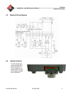
8.0 Lubrication
The HQ series actuators are totally enclosed units with a permanently lubricated gear trains (Moly EP
Grease). Once installed lubrication should not be required. However, periodic preventative maintenance
will extend the operating life of the actuator.
9.0 MDPI Settings
Manually rotate actuator to fully closed position
Remove actuator cover
Loosen indicator screw
Adjust indicator to correct orientation
Tighten indicator screw
Replace cover
Check indicator alignment