


VU443A; VU444A; VU843A; VU844A FAN COIL VALVE ACTUATORS
95C-10883—03 2
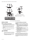
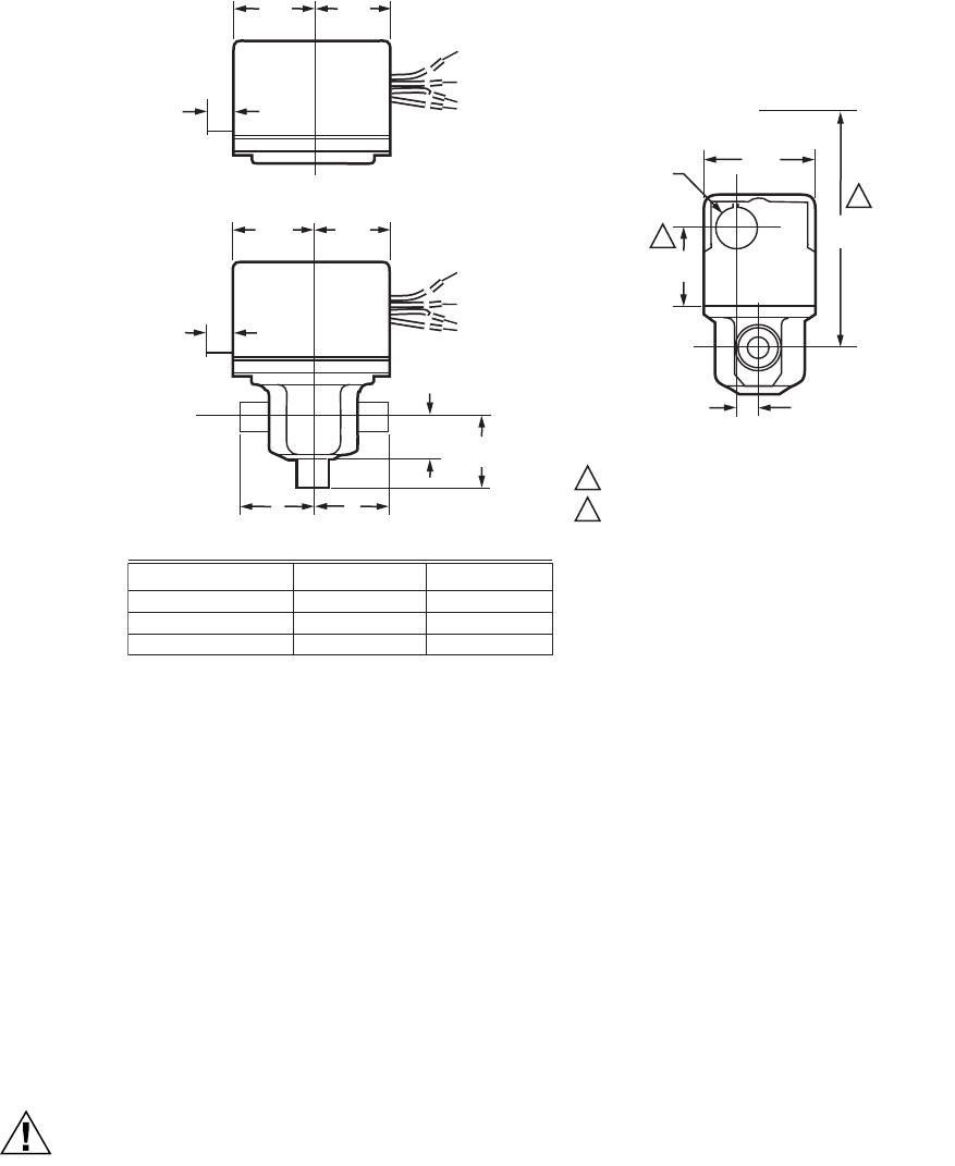
Fig. 1. Mounting Dimensions in inches (mm).
INSTALLATION
When Installing this Product...
1. Read these instructions carefully. Failure to follow them
could damage the product or cause a hazardous condi-
tion.
2. Check the ratings given in the instructions and on the
product to make sure the product is suitable for your
application.
3. Installer must be a trained, experienced service techni-
cian.
4. After installation is complete, check out product opera-
tion as provided in these instructions.
CAUTION
1. Disconnect power supply before connecting wir-
ing to prevent electrical shock of equipment dam-
age.
2. On 24V systems, never jumper the valve coil ter-
minals even temporarily. This can burn out the
heat anticipator in the thermostat.
To Install and Remove Actuator
INSTALLING ACTUATOR ON VU-SERIES VALVE BODY
ASSEMBLY
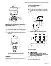
1. Orient slot in shaft of VU-series valve body toward
notch in side of body (i.e. 90° to water flow.) See
Fig.2. This lifts the ball off seat, prevents damage to the
ball seal while soldering, and makes actuator attach-
ment easier.
2. Install valve body into pipe.
3. Wiring connections may be made either before or after
the actuator is installed on the valve body.
4. Place manual operating lever on the actuator in the
MAN. OPEN position.
5. Line up motor coupling to slot in shaft of body and fit the
head onto the valve body, ensuring that the shaft seats
correctly. (See Fig. 2).
6. Snap actuator onto body by pressing down.
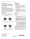
7. Make wiring connections. Refer to wiring section for
proper instructions.
Inspect the actuator installation and the valve body to ensure
that all connections and adjustments have been correctly
made. Adjust the thermostat or controller connected to the
valve so that the valve runs through its cycle. Make sure the
valve runs smoothly and positively from closed to open to
closed again.
VU52 OR VU53 VALVE WITH ACTUATOR
2-3/8
(60)
7/8 DIA. (22)
1-1/2
(38)
3-3/4
(133)
15/32 (12)
M32204
2
1
HEIGHT NEEDED TO REMOVE ACTUATOR OR COVER.
OPENING FOR 1/2 IN. CONDUIT ON OPPOSITE SITE OF
MANUAL LEVER FOR ALL MODELS.
1
2
VU53 AND VU54 VALVE DIMENSIONS WITH ACTUATOR
VU ACTUATOR
3/8
(10)
1-3/4
(44)
1-3/4
(44)
A
A
B
AB
3/8
(10)
A
1-3/4
(44)
1-3/4
(44)
B
3-WAY
7/8 (23)
2-WAY
VALVE BODY SIZE
1/2 IN. SWEAT
3/4 IN. SWEAT
1 IN. SWEAT
M32203
A
1-5/6 (33)
1-3/8 (35)
1-11/16 (43)
B
1-5/6 (33)
1-11/16 (43)
1-11/16 (43)