


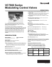

VC7900 SERIES MODULATING CONTROL VALVES
3 95C-10831—04
INSTALLATION
When Installing This Product...
1. Read these instructions carefully. Failure to follow them
could damage the product or cause a hazardous condi-
tion.
2. Check the ratings given in the instructions and on the
product to make sure the product is suitable for your
application.
3. Installer must be a trained, experienced service-person.
4. Always conduct a thorough checkout when installation is
completed.
5. While not necessary to remove the actuator from the
body, it can be removed for ease of installation. The actu-
ator can be installed in any position to suit the most con-
venient wiring direction. Actuator latching mechanism
works only when the lengths of the actuator and the
valve body are parallel to each other.
6. An extra 25 mm head clearance is required to remove
the actuator.
CAUTION
1. Disconnect power supply before connecting wiring
to prevent electrical shock and equipment damage.
2. On 24V systems, never jumper the valve coil termi-
nals, even temporarily. This may damage the thermo-
stat.
PLUMBING
The valve may be plumbed in any angle but preferably not with
the actuator below the horizontal level of valve body. Make sure
there is enough room around the actuator for servicing or
replacement.
For use in diverting applications, the valve is installed with the
flow water entering through bottom port AB, and diverting
through end ports A or B. In mixing applications the valve is
installed with inlet to A or B and outlet through AB.
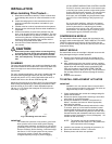
Mount the valve directly in the tube or pipe. Do not grip actuator
while making and tightening up plumbing connections. Either
hold valve body in your hand or attach adjustable spanner
(38 mm or 1-1/2") across the hexagonal or flat faces on the
valve body. (Figure 5).
Fig. 5. Plumbing of the VC valve.
IMPORTANT
For trouble-free operation of the product, good instal-
lation practice must include initial system flushing,
chemical water treatment, and the use of a 50 micron
(preferably 5 micron) 10% side stream system filter(s).
Remove all filter(s) before flushing. Limit flow through
the filter to 5~10% of total system flow to prevent
'starving' the system. Ensure filter cartridge is
changed frequently enough to prevent clogging.
Put the VC actuator manual lever in the manual open
or the fully open (down) position to allow initial system
flushing with the actuator mounted. This may be done
without electrical hook-up. Alternatively, reusable
flush caps, part # 272866B, may be purchased sepa-
rately for use in initial flushing of dirty hydronic sys-
tems.
Do not use boiler additives, solder flux and wetted
materials which are petroleum based or contain min-
eral oil, hydrocarbons, or ethylene glycol acetate.
Compounds which can be used, with minimum 50%
water dilution, are diethylene glycol, ethylene glycol,
and propylene glycol (antifreeze solutions).
COMPRESSION MODELS
For compression fitted models, tighten the compression nuts
enough to make a watertight seal. TAKE CARE NOT TO OVER
TIGHTEN. Maximum torque limit is 45 Nm (33 ft-lb) for the
22 mm compression fitting, and 65 Nm (48 ft-lb) for the 28 mm
compression fitting.
SWEAT MODELS
On sweat fitted valves, the cartridge is shipped loose to avoid
being damaged during the solder operation.
1. Remove valve actuator from body and solder the con-
necting pipes in accordance with normal soldering prac-
tices.
2. After soldering and valve has cooled, remove cartridge
assembly from plastic bag, insert into the valve body and
tighten down with enclosed wrench (part# 40007029-
002) until it bottoms out. DO NOT OVER TIGHTEN
(maximum torque is 4.5Nm [40 in-lb]). The top surface of
the cartridge will be flush with the top edge of the body
casting.
3. Replace valve actuator.
TO INSTALL REPLACEMENT ACTUATOR
IMPORTANT
Installation of a new actuator does not require drain-
ing the system provided the valve body and valve car-
tridge assembly remain in the pipeline.
1. Check replacement part number and voltage ratings for
match with old device.
2. Disconnect power supply before servicing to avoid elec-
trical shock or equipment damage.
3. Disconnect leadwires to actuator, or depress tab on
Molex™ connector and remove. Where appropriate,
label wires for rewiring.
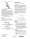
4. The actuator head is automatically latched to the valve.
To remove, press up on the latch mechanism located
directly below the white manual open lever with thumb
(See Figure 6). Simultaneously press the actuator down
towards the body with moderate hand force and turn the
actuator counter-clockwise by 1/8 turn (45 degrees). Lift
actuator off the valve body.
NOTE: The actuator can also be installed at right
angles to the valve body but in this position the
latch mechanism will not engage.
5. Install the new actuator by reversing the process in (4).
6. Reconnect leadwires or Molex™ connector.
7. Restore power, and check out operation.
M29716