MS4120F; MS4620F,S; MS8120F,S; S2024-F; S20230-F FAST-ACTING, TWO-POSITION ACTUATORS
63-2584—7 6
WIRING
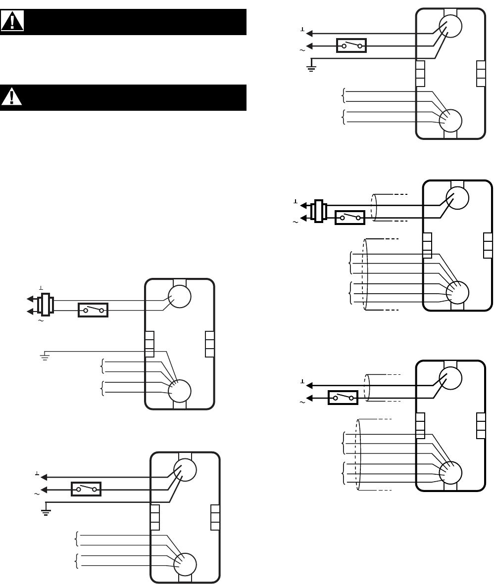
See Fig. 6 through 10 for typical wiring diagrams.
WARNING
Electrical Power Hazard.
Line voltage can cause death or serious injury and
short equipment circuitry.
Disconnect power supply before installation.
CAUTION
Electrical Shock or Equipment Damage Hazard.
Disconnect all power supplies before installation.
Motors with auxiliary switches can have more than one
disconnect.
IMPORTANT
1. All wiring must comply with local electrical codes,
ordinances and regulations.
2. Voltage and frequency of transformer used with
MS8120F,S and S2024-F must correspond with the
characteristics of power supply and actuator.
NOTE: The conduit fittings are designed for use with 3/8 in.
reduced-wall steel or aluminum flexible conduit.
Fig. 6. Typical 24 Vac wiring (MS Series).
Fig. 7. Typical 120 Vac wiring (MS Series).
Fig. 8. Typical 230 Vac wiring (MS Series).
Fig. 9. Typical 24 Vac wiring (S20 Series).
Fig. 10. Typical 230 Vac wiring (S20 Series).
M20053A
24 VAC
BLACK
RED
GREEN
MS8120F
L1
( )
L2
( )
YELLOW
YELLOW
BLUE
7° AUXILIARY
SWITCH
85° AUXILIARY
SWITCH
BLUE
M20056A
WHITE
BLACK
GREEN
MS4120F
L1
( )
L2
( )
YELLOW
YELLOW
BLUE
BLUE
7° AUXILIARY
SWITCH
85° AUXILIARY
SWITCH
120 VAC
M20057A
BLUE
BROWN
GREEN
230 VAC
MS4620F
L1
( )
L2
( )
YELLOW
YELLOW
BLUE
BLUE
7° AUXILIARY
SWITCH
85° AUXILIARY
SWITCH
M20678A
BLUE
BROWN
230 VAC
S2024-F-SW2, MS8120S
L1
( )
L2
( )
BLACK/BLUE
BLACK/RED
BLACK/YELLOW
GRAY/RED
GRAY/BLUE
GRAY/YELLOW
85° AUXILIARY
SWITCH
7° AUXILIARY
SWITCH
M20680A
BLUE
BROWN
230 VAC
S20230-F-SW2, MS4620S
L1
( )
L2
( )
BLACK/BLUE
BLACK/RED
BLACK/YELLOW
GRAY/RED
GRAY/BLUE
GRAY/YELLOW
7° AUXILIARY
SWITCH
85° AUXILIARY
SWITCH


