MS4120F; MS4620F,S; MS8120F,S; S2024-F; S20230-F FAST-ACTING, TWO-POSITION ACTUATORS
63-2584—7 4
INSTALLATION
When Installing this Product...
1. Read these instructions carefully. Failure to follow
them could damage the product or cause a hazardous
condition.
2. Check the ratings given in the instructions and on the
product to make sure the product is suitable for your
application.
3. Installer must be a trained, experienced service
technician.
4. After installation is complete, check out product
operation as provided in these instructions.
WARNING
Electrical Power Hazard.
Line voltage can cause death or serious injury
and short equipment circuitry.
Disconnect power supply before installation.
CAUTION
Electrical Shock or Equipment Damage Hazard.
Low voltage can shock individuals or short
equipment circuitry.
Disconnect power supply before installation.
IMPORTANT
All wiring must agree with applicable codes,
ordinances and regulations.
Location
The actuators are designed to open a damper by driving the
damper shaft in either a clockwise or counterclockwise
direction. The actuator housing has two slots on the
bottom, either of which, with a 205649 Mounting Bracket,
secures it flush to a damper box (see Fig. 2).
NOTE: When mounted correctly, these slots allow the
actuator to float without rotating relative to the damper
shaft.
CAUTION
Equipment Damage Hazard.
Tightly securing actuator to damper housing can
damage actuator.
Mount actuator to allow it to float along its vertical axis.
Preparation
Before mounting the actuator onto the damper shaft, determine
the:
— Damper/valve opening direction for correct spring return
rotation. The actuator can be mounted to provide clockwise
or counterclockwise spring return.
— Damper shaft size (see Specifications section).
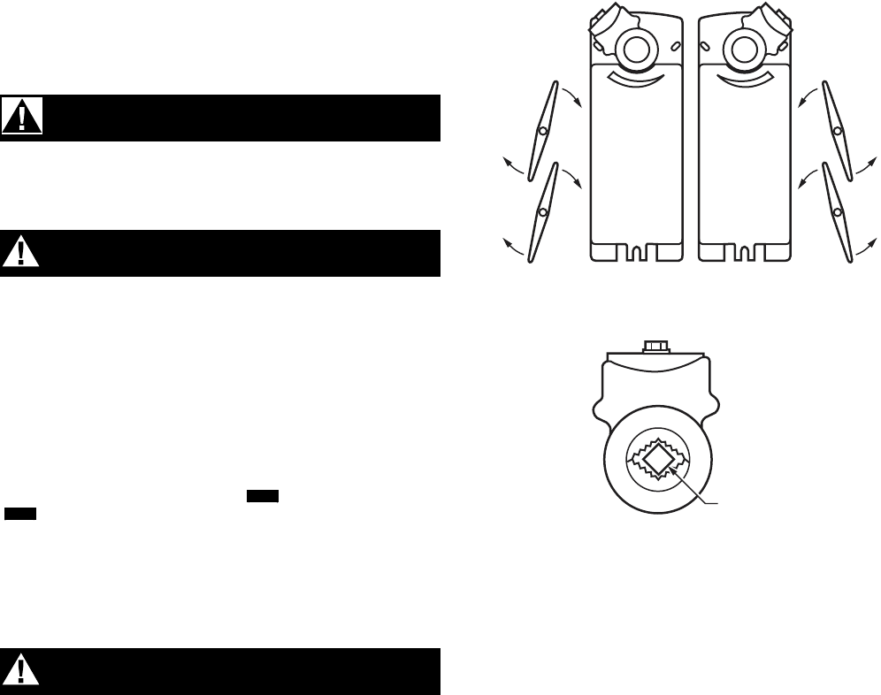
Determine Appropriate Mounting Orientation
See Fig. 2 for mounting orientation.
NOTES:
— Actuators are shipped in the fully closed position.
— An arrow molded into the hub points to tick marks
on the label to indicate the hub rotary position.
— See Fig. 3 for proper mounting to a square damper
shaft.
Fig. 2. Spring Return DCA mounting orientation.
Fig. 3. Proper mounting to square damper shaft.
Measure Damper/Valve Shaft Length
If the shaft is less than three inches in length, the shaft
coupling must be located between the damper/valve and
actuator housing. If the shaft length is more than three inches,
the shaft coupling may be located on either side of the actuator
housing.
If the coupling must be moved from one side of the actuator to
the reverse, follow these instructions (see Fig. 4):
1. Remove the retainer clip from the shaft coupling and set
it aside for later use.
2. Remove shaft coupling from one side of the actuator.
3. Replace the shaft coupling on the opposite side of the
actuator aligning it based on the stroke labelling.
4. Replace the retainer clip on the shaft coupling using the
groove of the coupling.
M20052
CCW TO CLOSE
(FAIL-SAFE
POSITION)
CW TO OPEN
CW TO CLOSE
(FAIL-SAFE
POSITION)
CCW TO OPEN
DAMPER SHAFT
M21007


