N20, N34 SERIES MN7220, MN7234
63-2587—1 4
Voltage/Current Control Signal Selection Dip Switch
In its default shipping position, the voltage/current control
signal dip switch (see Fig. 4) is set to OFF (= voltage control).
as shown in Fig. 4. Setting it to ON results in current control.
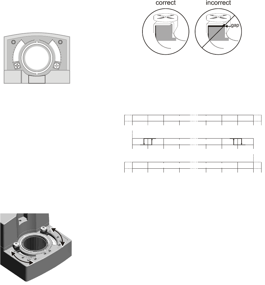
Position Indication
The hub adapter indicates the rotation angle position by means
of the rotational angle scales (0...90° / 90...0°).
Fig. 6. Position indication
Manual Adjustment
IMPORTANT
In order to prevent equipment damage, you must
remove power before manual adjustment.
After removing power, the gear train can be disengaged using
the declutch button, permitting the actuator shaft to be
manually rotated to any position. The feedback signal will then
follow the new position.
Limitation of Rotation Stroke
Two mechanical end limits (adjustable in 3° increments) are
provided (20 Nm [175 lb-in] models, only) to limit the angle of
rotation as desired (see Fig. 7).
Fig. 7. Mechanical end limits
The mechanical end limits must be securely fastened in place
as shown in Fig. 8. Correct / incorrect tightening of end limits8.
Specifically, it is important that they properly mesh with the
rotational angle scales when the screws are tightened.
Fig. 8. Correct/incorrect tightening of end limits
Internal Auxiliary Switches
The internal auxiliary switches are set to change from
“common” to “normally open” at angles of 5° and 85°,
respectively, from the totally counterclockwise position.
Fig. 9. Internal auxiliary switches
Override
If terminal 3 of the terminal strip (see section “Wiring
Diagrams” on page 6) is unplugged, the stroke will be 0%;
reversing the rotation direction using the rotation direction
switch will result in a max. stroke of 100%. If terminal 3 is
jumped with terminal 1 (24 V), the stroke will be 50%.
INSTALLATION
These actuators are designed for single-point mounting.
IMPORTANT
In order to prevent equipment damage, you must
remove power or set the rotation direction switch to
the “Service/Off” position before manual operation.
Mounting Instructions
All information and steps are included in the Installation
Instructions supplied with the actuator.
90 90
60
30
60
30
00
5° 10° 15° 92.5
0° 90°-2.5° 85°80°75°
85° 80° 75° -2.5°90° 0°92.5° 5°10°15°
5° 10° 15°0° 90°85°80°75°
CCW internal
auxiliary switch
CW internal
auxiliary switch
actuator scale: clockwise
auxiliary switch scale
actuator scale: counterclockwise


