


ML7984B
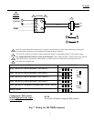
WIRING
4
24 Vac
1
2
ML7984B
L1
L2
T5
T6
R
W
C
3
SIGNAL
SOURCE
B
+
2-10 Vdc
PWM
OR
+
T6
28 Vdc
-
T5
1
3
2
4
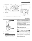
Allow 0.5 amps maximum for each device. Actuators and controller can share same transformer providing the
VA rating of the transformer is not exceeded and proper phasing is observed.
"T5" and "W" terminals are factory connected internally. Device is compatible with the 3-wire control system.
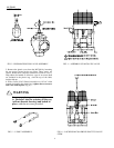
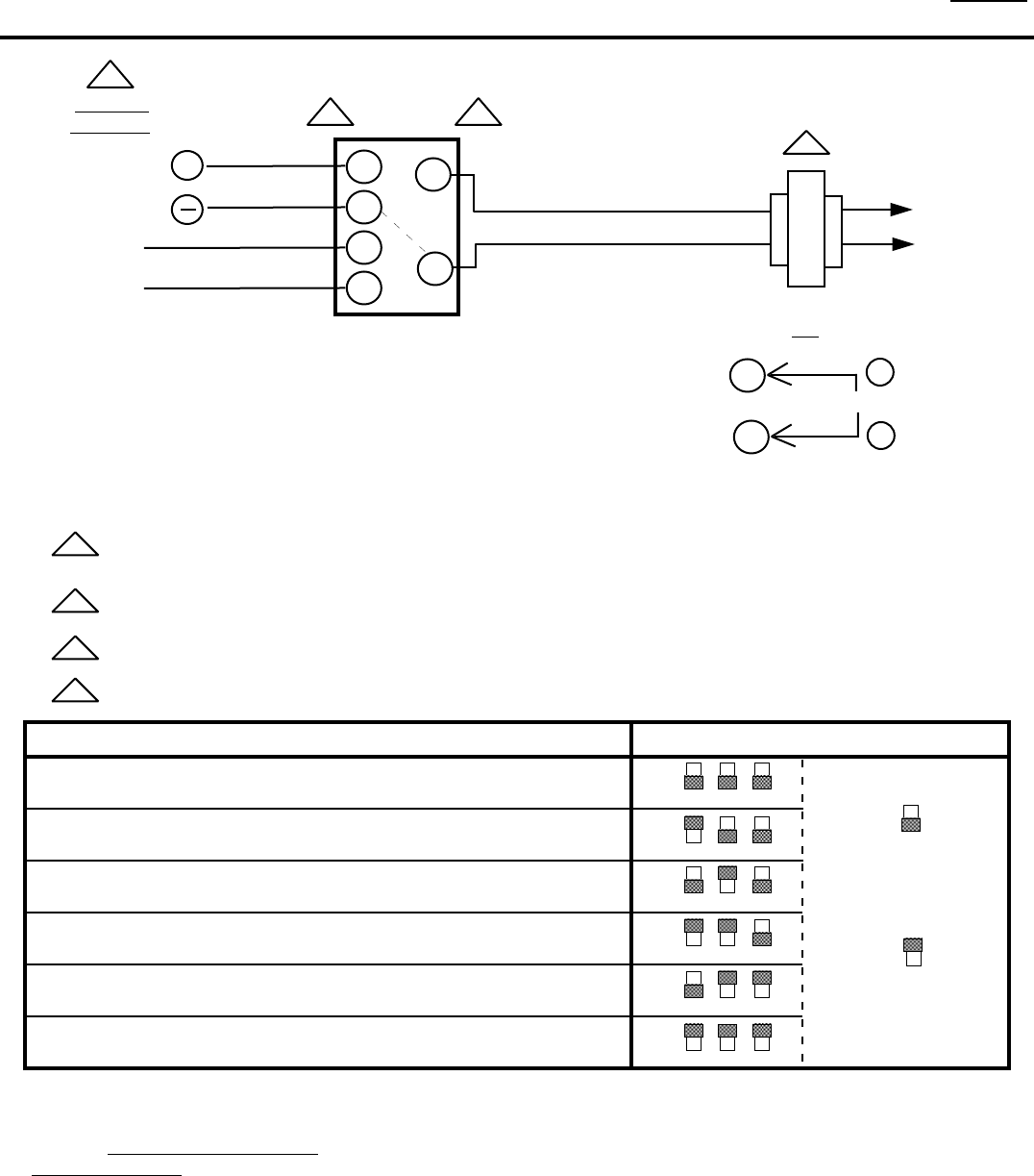
Use configuration DIP switches to select device functions: Direct acting function ( actuator stem moves upwards
with signal increases ) or Reverse acting function ( actuator stem moves downwards with signal increases ).
Use either one controller only
1
2
3
on
off
4
on
off
Reverse
Acting
4
on
off
Direct
Acting
MODE DIP SWITCH
PWM: min. 0.1 sec + 0.01 sec increments (max. 2.65 sec )
PWM: min. 0.1 sec + 0.02 sec increments (max. 5.20 sec )
PWM: min. 0.1 sec + 0.05 sec increments (max. 12.85 sec )
PWM: min. 0.1 sec + 0.10 sec increments (max. 25.6 sec )
PWM: min. 0.59 sec + 0.00918 sec increments (max. 2.93 sec ) NOVAR
Analog: 2-10 Vdc
1
2
3
on
off
1
2
3
on
off
1
2
3
on
off
1
2
3
on
off
1
2
3
on
off
Configuration DIP switches
NOTE:
located adjacent to the input
Turn power off before setting the DIP switches.
terminal block
Fig. 7 Wiring for ML7984B actuators
5