


63-2505 G.R. 06-04 www.honeywell.com
Automation and Control Solutions
Honeywell International Inc. Honeywell Limited-Honeywell Limitée
1985 Douglas Drive North 35 Dynamic Drive
Golden Valley, MN 55422 Scarborough, Ontario
M1V 4Z9
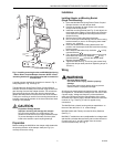
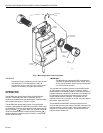
ML6284 NON-SPRING RETURN DIRECT COUPLED DAMPER ACTUATOR
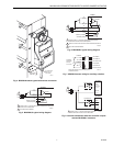
Fig. 9. Common transformer with two controller outputs
and two ML6284D,F actuators.
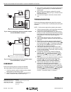
Fig. 10. Common transformer with one controller output
and two ML6284A,C actuators.
CHECKOUT
Perform the following steps to checkout the ML6284
Non-Spring Return Direct Coupled Damper Actuator.
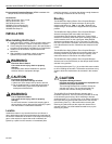
1. Check the actuator position indicator and the damper
shaft position to see that they agree.
2. If the actuator has time-out function, apply 24 Vac to
black (T1) lead and red (T2) lead. See Fig. 5.
3. Apply 24 Vac control signal to blue (B) lead with respect
to black (T1) lead (see Fig. 5). Actuator should drive
damper open.
4. Apply 24 Vac control signal to yellow (W) lead with
respect to black (T1) lead (see Fig. 5). Actuator should
drive damper closed.
5. If 24 Vac control signal is removed, actuator should
stop.
TROUBLESHOOTING
Perform the following troubleshooting steps if the actuator
does not drive, travel full stroke, or operate properly during the
checkout.
NOTE: Perform these steps before replacing the actuator.
1. Check the actuator label to verify that proper power and
control signal requirements have been met.
2. Check for 24 Vac at actuator black (T1), yellow (W) or
blue (B), and red (T2) [if actuator has time-out function]
leads when the actuator should be driving. If the voltage
is not present or is low, check power supply and
controller.
3. If the actuator does not drive in the correct direction
when a control signal is applied, reverse the yellow and
blue wires.
4. Remove power and fully depress and hold disengage
button down while turning damper shaft clockwise
and counterclockwise . If the damper shaft turns
freely through the entire 90¡ stroke and the actuator is
installed correctly, replace the actuator.
5. If the damper shaft will not turn freely for the full 90°
check for any bind and make sure the actuator is loose
on the mounting bracket. If necessary, adjust mounting
bracket to prevent binding.
6. If no binding is noticed in the actuator and damper
assembly, remove the actuator and turn the damper
shaft clockwise and counterclockwise . If
the damper does not turn freely, repair or replace the
damper.
7. If the damper turns, fully depress and hold the actuator
disengage button down and turn the actuator hub
clockwise and counterclockwise . If the
actuator hub does not turn, replace the actuator.
8. If the actuator and damper turn freely, remount the
actuator to the damper in accordance with the
instructions in the Installation section. Make sure the
actuator and mounting bracket do not bind. Make sure
the actuator and damper are both at the same end stop
(clockwise or counterclockwise ) when they
are assembled. Hook up the wires and repeat the
checkout. Troubleshoot again, if necessary.
L1
(HOT)
L2
1
1
RED
BLACK
RED
BLACK
ML6284D,F
ML6284D,F
M4886A
POWER SUPPLY. PROVIDE DISCONNECT MEANS
AND OVERLOAD PROTECTION AS REQUIRED.
CONTROLLER
CONTROLLER
BLUE
YELLOW
BLUE
YELLOW
L1
(HOT)
L2
1
1
BLACK
BLACK
ML6284A,C
ML6284A,C
M4887A
POWER SUPPLY. PROVIDE DISCONNECT MEANS
AND OVERLOAD PROTECTION AS REQUIRED.
CONTROLLER
BLUE
YELLOW
BLUE
YELLOW