


INSTALLATION AND CHECKOUT CONTINUED
Automation and Control Solutions
Environment Control Products
1985 Douglas Drive North
Golden Valley, MN
55422-3992
This material is proprietary to
Honeywell Limited and shall not be
reproduced, copied or used in any manner
without prior written consent of Honeywell Limited.
Helping You Control Your World
M847D
In Canada:
Honeywell Limited
35 Dynamic Drive
Toronto, ON
M1V 4Z9
Printed In Canada
Replacing M847D on aTrol-A-Temp® ARD damper
1. Disconnect the motor wiring.
2. Using a 1/8 in. hex wrench to loosen the motor coupling from
the blade shaft, remove the existing motor assembly.
3. Observe that the damper blades are in the normal, spring
open or spring closed position.
4. Place the new motor onto the shaft and tighten the coupling.
5. Reconnect the motor wiring.
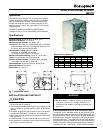
ALTERNATE MOUNTING (For 7/16"dia. coupling style
dampers)
Before installing the M847D actuator to a damper with a 7/
16" coupling, insert the drive shaft extension into the drive
shaft and tighten with the set screw provided. See Fig. 2.
Also install the anti-rotation extension to the end of the
anti-rotation rod. Install the actuator on the damper and
tighten the coupling screw.
CHECKOUT
After completing the installation, check that the equipment
operates correctly as follows:
1. When 24 Vac is applied to the motor leads, the motor powers
to the closed or open position.
2. When power is removed, the motor releases and spring
returns to the normal position.
If full opening and closing is not achieved, check the lower
adjustment lever is to the extreme left and the upper lever is to
the extreme right. See Fig. 4 (Air Flow Adjustments)
Replacing M847D on aTrol-A-Temp® ZDS or ZDB damper
1. Disconnect the motor wiring.
2. Using a 3/16 in. hex wrench to loosen the Allen screw located
above the faceplate at the motor coupling.
3. Remove the existing motor.
4. Observe that the damper blades are in the open position with
the setscrew pointing toward the damper label.
5. Attach the new motor to the coupling. Make sure that the
standoff on the motor is positioned in the grommet on the
faceplate.
6. Tighten the set screw.
7. Reconnect the motor wiring.
Fig 2. For 7/6" COUPLING MODEL DAMPERS ONLY
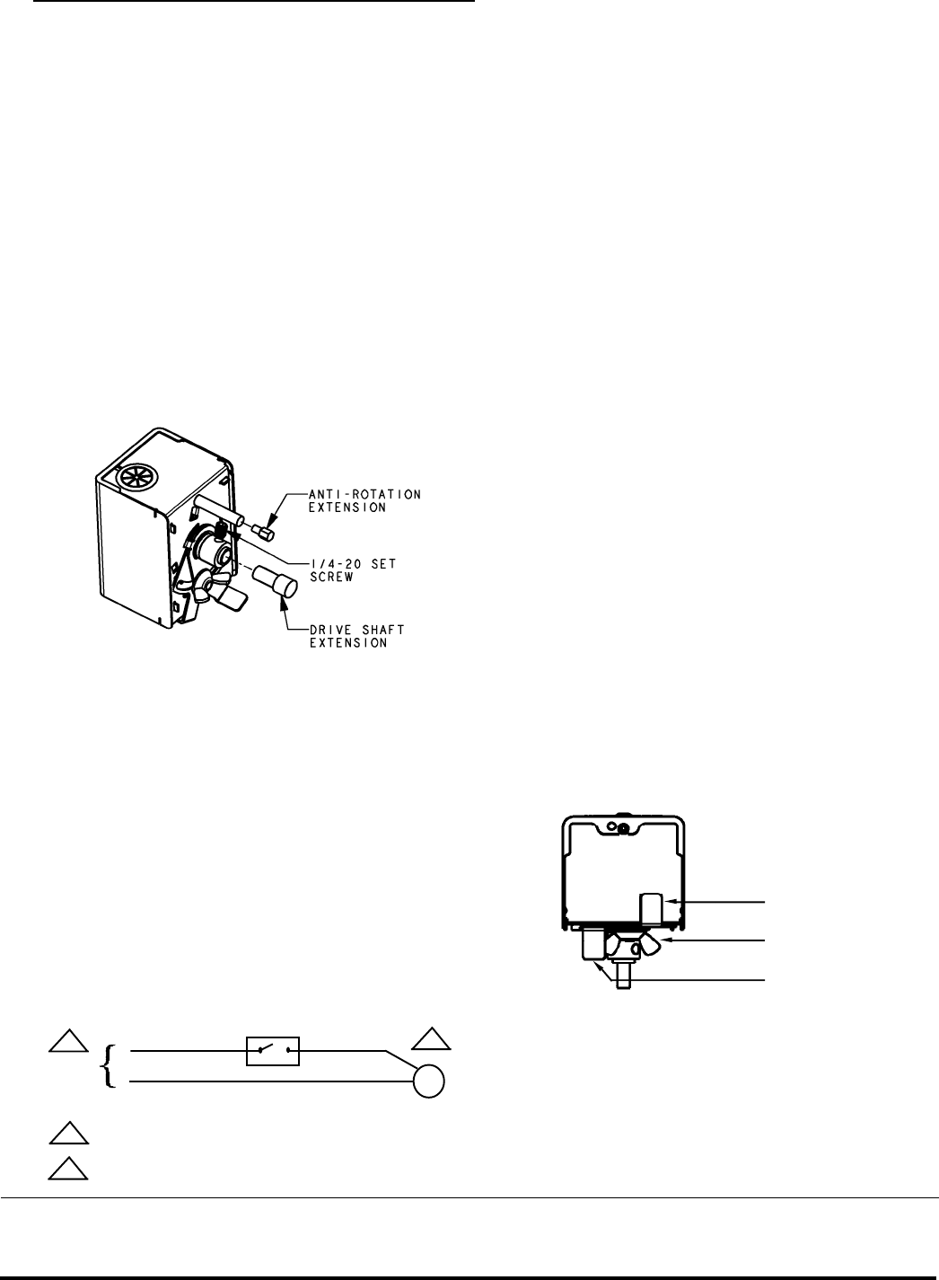
WIRING
See Figure 3. for typical wiring hook-ups of the M847D.
Figure 3 - Typical M847D Hookup
Zoning Switch
Orange
Yellow
Operator
Motor
2
24 VAC
60 Hz
1
PROVIDE DISCONNECT MEANS AND OVERLOAD
PROTECTION AS REQUIRED.
NOMINAL CURRENT 0.32 AMP
1
2
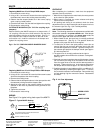
AIR FLOW ADJUSTMENTS
Note: The following describes the adjustments available with
the actuator installed in the power closed mode. If the damper
you are installing is to operate in the power open mode, the
function of the upper and lower levers is reversed.
1.When viewed on end, the lower lever is normally positioned
to the extreme left. (See Fig. 4) This position allows the
damper to fully open 90° when de-energized.
2.To restrict the air flow in the open position, loosen (do not
remove) the wing nut and move the lower lever to the right
until the desired position is reached. Tighten the wing nut. In
the extreme right position the damper should open approx.
50° with the power off.
3.The upper lever is normally positioned to the right to
provide complete shut off when the acutuator is energized.
(See Fig. 4)
4.If desired, to prevent complete closure of the damper, loosen
(do not remove) the wing nut on the bottom of the unit and
move the upper lever to the left until the desired position is
achieved. Tighten the wing nut. In the extreme left position
the damper should close to approx. 40° with the power on.
5.If additional rotation is required beyond 90°, an additional 15°
may be obtained by removing the Upper Lever. To do this,
first, remove the actuator from the damper. Remove the wing
nut and retaining ring then remove the levers. Reassemble
and install.
UPPER LEVER
WING NUT
LOWER LEVER
Fig. 4 - Air Flow Adjustment