


5
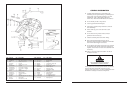
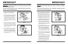
14. Secondary Lock Installation:
A. Pre-install the secondary lock (10) in the
closed position in the casting. Do not
install the spring, release handle or the
secondary lock pin yet. Align the
secondary lock pin holes. Rotate the
secondary lock until it makes contact
with the casting at point (
C) as shown in
Figure 9. Check the rough location of the
end of the secondary lock in relation to
the swinging lock. It should be 3/16”
(0.188”) ± 1/16” (0.06”) from point (
A)
on the swinging lock (see Figure 9) when
secondary lock is resting against the
casting at point (
C).
B. If the dimension is less than 1/8” (0.125”),
remove the secondary lock (10) and place
a bead of weld on the fifth wheel casting
at point (
C) and grind smooth. If the
dimension is greater than 1/4” (0.25”),
remove the secondary lock and grind at
point (
D) as shown in Figure 10.
C. After a final check of the dimensions, coat
the lock pin hole in the secondary lock
(10) with Never-Seez
®
(supplied with kit).
DO NOT use any substitute lubricant.
D. Install the secondary lock release handle
(9) into the casting. Install the secondary
lock (10) onto the handle. Install cotter
pin (
8) in handle and spread the cotter
pin. Drive the secondary lock pin (3)
through the holes in the casting and the
secondary lock and secure with cotter pin
(
2). Install grease fitting (25) in lock pin
so that fitting faces the side and will be
accessible from the left side of the tractor.
Install spring (
11) by fitting the small
diameter end over the projection on the
secondary lock (
10) and the large
diameter end into the spring pocket in
the casting.
15. Adjust the Fifth Wheel Locks:
Leave lock tester in closed locks for this
procedure: Using a ratchet with 1/2” Allen
wrench, tighten the adjustment screw (
20)
in the throat in the fifth wheel by turning
the screw clockwise until tight. Check that
the kingpin on the lock tester is square to
the swinging lock (
6) and that the
stationary lock is square to the kingpin. If
not square, align the kingpin and/or
stationary lock as necessary and retighten
the adjusting screw. Tighten lock nut (
19) on
the stationary lock. Loosen the adjustment
screw (
20) by turning counterclockwise 1
1
⁄2
turns. The locking mechanism is now
properly adjusted.
16. Check that the secondary lock operates freely.
17. Check the operation of the fifth wheel by
locking and unlocking several times.
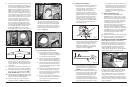
Checking the Operation of the Fifth Wheel:
With the fifth wheel upright, it will function as
follows: When the swinging lock (6) is open, the
release handle (16) will be in; the plunger (17)
will extend into the throat area such that the
step in the plunger is visible in the throat, as
shown in Figure 11, and the secondary lock
release handle (18) will be out with the handle
lug disengaged from the top plate casting.
Fifth Wheel Coupling:
As the lock tester is coupled to the fifth wheel,
the swinging lock closes, pushing the plunger
(17) back and the release handle (16) out.
As the swinging lock closes, the secondary lock
spring will move the secondary lock into the
closed position behind the swinging lock and
move the release handle inward. When properly
locked, the locking plunger (
17) will be visible as
shown in Figure 11.
D
GRIND FLUSH IF NECESSARY BUT
DO NOT EXCEED FLUSH CONDITION
Figure 10
Figure 11
3/16 1/16
A
C
Figure 9
PLUNGER STEP
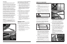
6. Check travel of the plunger. With the release
handle in the closed position, the edge of
the release lever (15) should be a maximum
of 1/2” from the top plate casting rid (see
Figure 4). If this condition does not exist,
check if the rounded end of the release lever
(
15) is passing under the guide rib of the
casting, as shown in Figure 5.If the rounded
end is hitting the rib, bend the rounded end
of the release lever (15) down so that is goes
deeper into the plunder slot. If the release
lever is still greater than 1/2” from the
casting rib, remove the release lever and
bend it as shown in
Figure 6 until it is less
than 1/2” from the casting. If the square
end of the release lever (15) and/or end of
the release handle (
16) is hitting the casting
rub (see Figure 4), grind the corner of the
release lever (15) and/or the end of the
handle (
16) until it is clear of the casting rib.
7. Install the stationary lock (6) in the casting
with the large counterbore facing down.
Install the lock nut (19) onto the jaw and
tighten until tight, but still allowing the lock
to rotate slightly to ensure alignment with
the kingpin.
8. Apply grease to spring (7) and install it into
the casting. Position it as shown in
Figure 7.
9. Coat the lock pin hole in the swinging lock (6)
with Never-Seez
®
(supplied with kit). This is
VITAL. DO NOT USE any substitute lubricant.
10. Before installing the swinging lock (6), you must
place the secondary lock (10) into its approximate
location in the casting (see Figure 9).
11. Place the swinging lock (6) into position
compressing spring (7). Note: The lock pin
(
5) has a hole for a grease fitting. Position
the pin so that the hole faces the front of
the casting. Drive the lock pin (
5) through
the holes in the casting and swinging lock
and secure with cotter pin (
4). Install the
grease fitting so that it faces to the side and
will be accessible from the left side of the
tractor. (See Figure 8).
12. Turn the fifth wheel upright.
13. Check the Primary Lock Operation:
A. Lock the fifth wheel using a Holland
TF-TLN-5001 (2”) lock tester or Holland
TF-TLN-1500 (3
1
⁄2”) lock tester (as appropriate
for the fifth wheel being rebuilt).
B. Pull the primary release handle (16) out,
raise it up and engage the handle lug
with the top plate casting (see Figure 13).
C. Pull the primary release handle (16) out
further and install a small piece of 1/4”
stock (not supplied) between the handle
lug and the casting.
D. Unlock the fifth wheel by removing the
lock tester. When operating properly,
this action will drop the 1/4” stock and
the release handle will drop down and
move to the locked position.
E. If the 1/4” stock does not drop out, go
back to Step 6 and bend the release arm
(15) slightly in the opposite direction.
F. Repeat Step D, above.
SUPPORT HERE
BEND HERE
Figure 6
4
Figure 5
Figure 7
Figure 8