


Page 4
SKU 94641
For technical questions, please call 1-800-444-3353.
Warning!! Stand clear of the Jack when raising or lowering a vehicle.
1. Jack Capacity.
Never exceed the Jack’s capacity of 10,000 Lbs. (5 Tons). Check the vehicle’s
owner’s manual to determine the actual gross weight of your vehicle before attempting to lift
it.
2. Never ride on the Jack. Never ride on the Jack, and never have people or pets in the vehicle
you are raising.
3. Only use Jack to raise vehicle. After raising the vehicle, use jack stands to keep the vehicle
suspended for periods of time. Do not work on or under the vehicle while it is supported by
the Jack. The Jack is designed for lifting the vehicle only.
4. Place Jack on correct surface. Only use this Jack on a stable, level, clean and dry surface
that is capable of sustaining the load.
5. Stabilize the load. Ensure that the load remains stable at all times. Do not move the load
while it is on the Jack.
6. Vehicle lifting. When lifting a vehicle, apply the emergency brake and block all of the wheels
that will remain on the ground.
7. Center load. Center the load on the Jack Saddle (7.1). Off-center loads can damage seals,
causing Jack failure.
8. Lift only using correct vehicle lift points. Read the vehicle manual to find the proper lifting
points for the vehicle.
9. Never use the Jack unless it is filled with hydraulic fluid. Filling with hydraulic fluid is
covered in the maintenance section of this manual.
10. NEVER USE THIS JACK FOR AIRCRAFT PURPOSES.
11. Caution: Always be aware of Dynamic Loading. If you drop a weight on the Long
Frame Jack, it may create for a brief instant, an excess load. The Long Frame Jack is
designed for a maximum load of 10,000 lbs.; do not exceed this lifting capacity.
12. Bypass Valve (6.34) is preset by the factory and must not be adjusted by the user. Any
adjustment in the Bypass Valve could result in failure of the jack, personal injury and/or
property damage.
Specific Jack Safety Precautions
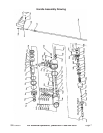
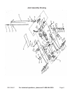
Assembly
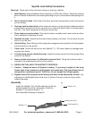
Handle (1.5)
Saddle (7.1)
Foot Pedal (2.1)
Handle Fork (2.4).
Insert the Handle (1.5) into the opening on the top
of the Handle Fork (2.4), and secure it with the
Washer (1.6) and the Screw (1.7).
See Assembly Drawings on page 8.