


SKU 66632 For technical questions, please call 1-800-444-3353. Page 3
OPERATION
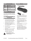
Test Button
Display
Photo Source
Memory Button
Socket for
AC Adapter
Figure 2
1. Cut a 3/4” length of reective tape (in-
cluded), peel off the backing and attach the
reective tape to the object to be measured.
Note: The longer the piece of reective tape, the
easier it is to make the measurement.
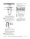
Point the Tachometer’s Photo Source at the 2.
reective tape on the object, holding the tool
approximately 2” to 8” away.
Start the object turning.3.
Turning
Reective Tape
Figure 3
4. Press and hold the Test Button, keeping the
beam of light perpendicular to the reective
tape surface.
After several seconds, a reading will appear 5.
on the Display. When the reading is stable, or
near stable, note the reading on the Display
and then release the Test Butoon.
Note: If the reading fails to appear, adjust the
Tachometer’s angle so that it is perpendicu-
lar to the reective tape on the object and/or
adjust the distance between the Tachometer
and the reective tape.
After the test button is released, the maxi-6.
mum, minimum and last readings of the
measurements are stored.
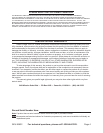
Symbol Key
Low Battery Indicator:
-Batteries are low and need replacing
Maximum reading is displayed
Minimum reading is displayed
Photoelectricity mode symbol
Revolutions per minute (RPM)
Figure 4
7. To access the readings, press and release
the Memory Button repeatedly to cycle
through the readings on the Display. The
indicators above the digits will appear as
described in Figure 4.