


Page 4SKU 32916
Assembly
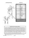
Refer to the Assembly Drawing on page 6 and the pictures below and on the cover.
1. Insert the Middle Beam (#17) into the bottom of the Post (#3). Line up the hole in the
middle of the Rear Beam (#6) with the hole on the bottom of the Middle Beam (#17) and use
a Bolt (#9) and a Washer (#24) to secure both the Middle Beam (#17) and the Rear
Beam (#6) to the Post (#3). See FIGURE 1 and the Assembly Drawing on page 6.
2. Attach the four Holders (#20)
to the Plate (#21) with Bolts (#18),
Washers (#19), and Nuts (#22).
See FIGURE 2 and the Assembly
Drawing on page 6.
3. Insert the Plate (#21) assembly
into the tube on top of the Post (#3)
and secure it with the Pin (#1).
4. Put the Handle Sleeve (#4) on
the Handle (#2) and secure it to
the Handle (#2) on the Post (#3)
with the Split Pin (#25).
See FIGURE 2 and the Assembly
Drawing on page 6.
FIGURE 2
Holder (#20)
Plate (#21)
Bolt (#18)
Washer (#19)
Nut (#22)
Tube
Pin (#1)
Handle (#2)
Split Pin (#25)
5. Attach the Front Cross Beam (#16) under the Bracket, to the Middle Beam (#17) using
Bolts (#5), Washers (#7), and Nuts (#8). See FIGURE 1 and the Assembly Drawing.
6. Attach the Caster (#13) plate to the metal tabs on the Front Cross Beam (#16) using four
Bolts (#23), Washers (#26), Spring Washers (#14) and Nuts (#15). Repeat with the other
Caster (#13). See the Assembly Drawing on page 6.
Note: After assembly, test if the Stand rolls properly, if the hardware is secure, and practice
using the Handle (#2) and rotating the Plate (#21). Check it for cracks, bends in the metal, or
signs of unusual wear. If any are found, do not use the Stand. Take it to an authorized
technician for service or repair.
Post (#3)
Rear Beam (#6)
FIGURE 1
Middle Beam (#17)
Bolt (#9) enters from underneath (not shown)
Front Cross Beam (#16)
Bracket