


Installation
4 3A1767A
Installation
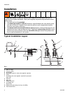
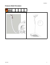
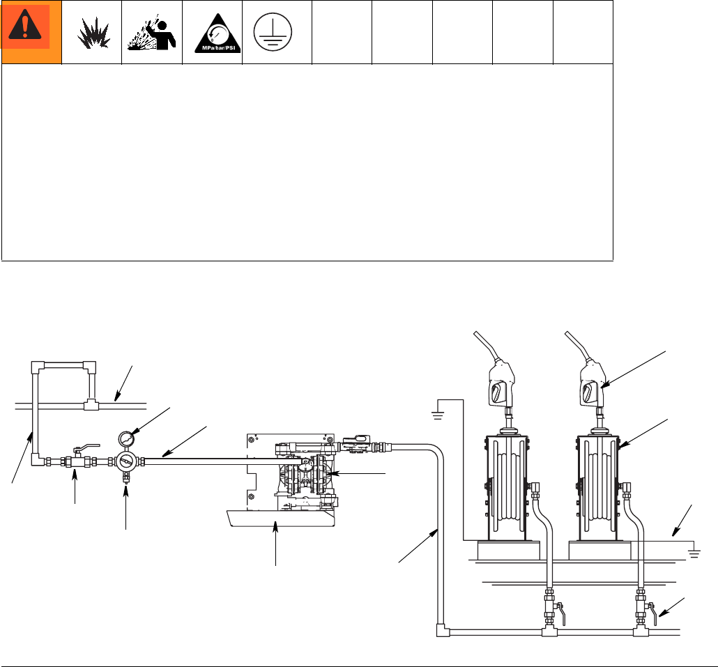
Typical Installation Layout
A Main air supply
B Pump air supply
C Air regulator
D Bleed-type master air valve (user supplied, required)
EPump
F Grounding wire (user supplied, required for pump and
hose reel)
G Fluid line
H Hose reel
J Dispensing valve
K Air Supply Line
L Nozzle Tray
M Safety Valve (set to 50 psi (3.4 bar, 03.4 MPa)
N Fluid Shutoff Valve
A bleed-type master air valve (E), thermal relief valve (H) and fluid drain valve (J) are
required in your system installation. These (user supplied) components help reduce the risk of
serious injury.
• The hose reel must be grounded.
•The bleed-type master air valve (E) relieves air trapped between this valve and the pump
after the air is shut off. Trapped air can cause the pump to cycle unexpectedly, therefore
locate the valve close to the pump.
•The thermal relief valve (H) and fluid drain valve (J) assist in relieving fluid pressure in the
displacement pump, hose and dispense valve. Triggering the dispensing valve (N) to relieve
pressure may not be sufficient. Open the fluid drain valve (J) to relieve fluid pressure that
may be captured elsewhere in the system.
F
IG. 1
B
A
C
D
E
F
G
J
H
ti13981
P
K
K
L
N
M
G
A
B
C
D
E
F
G
H
J
K
L
M
N
.