


Installation
8 3A1189G
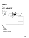
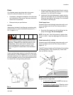
The suction line is designed to allow for full evacuation
of the container so it will bend slightly when installed.
1. Connect suction tube (6c) to drum insert (6b) to
pump.
2. Insert suction line (6c) into drum.
3. Install drum coupler (6a) into drum insert (6b)
4. Connect hose (E) to pump fitting. Use a flat-blade
screw driver to tighten hose clamp (F).
5. Connect the air supply line (C) to the air controls.
Nozzle (3) Installation: Models 24F878 and
24F947
Numerals used in the following instructions refer to ref-
erence numbers used in the Parts Lists provided on
pages 10 - 11.
Wall Mount Model: 24F878
1. Install hose (9) into back of nozzle (3). Wrench
tighten.
2. Install other end of hose (9) into pump outlet fitting.
Drum Mount Model: 24F947
1. Install clamp over end of fluid supply hose (9).
2. Push end of fluid supply hose (9) over end of nozzle
(3) fitting.
3. Position clamp over fitting and hose end. Use a flat
blade screw driver to tighten screw and secure
clamp to the end of hose over barbed fitting.
4. Install other end of hose (9) into pump outlet fitting.
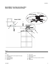
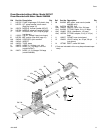
Meter (10) Installation: Models 24F531 and
24M499
Uses Meter Kit 24H293 that includes the following parts:
-Meter (10a), Swivel (10b), Fitting (10c) and Seal (10d)
and Fitting (10e).
1. Install hose (9) into back of nozzle (3). Wrench
tighten.
2. Install pipe swivel fitting (10b) into pump outlet.
Wrench tighten.
3. Install fitting (10c) into swivel (10b). Wrench tighten.
4. Install meter (10a) to fitting (10c). Wrench tighten.
5. Install fitting (10e) into meter. Wrench tighten.
6. Install hose (9) into fitting (10e).
Mounting Bracket (2) Installation
• When installing bracket, be sure the mounting sur-
face can support the weight of the pump, hoses and
all accessories, as well as the stress caused during
operation.
• On all installations mount the pump using screws
and nuts provided.
• Always keep nozzle bath tray filled with water.
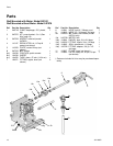
Wall Mounting Kit 24F870 (2): Models 24F531 and
24F878 only
Wall mounted DEF System Models 24F531 and 24F878
include a Mounting Bracket Kit containing the following
parts - Screws (2a), Screws (2b), Washers (2c), Plain
Washers (2d), Hex Nuts (2e), Mounting Plate (2f), Noz-
zle Bath Holder (2g), Nozzle Holder Bracket (2h) and
screws (2j). The Mounting Bracket and Nozzle Holder
are also identified as items J and M on the Typical
Installation Diagram provided on page 4.
1. Determine location to install mounting plate (2f).
2. Use holes the plate (2f) as a template. Mark mount-
ing hole locations. Use a drill to predrill mounting
holes in mounting surface.
3. Use screws (2a) (provided) to install plate (2f).
4. Align holes in nozzle holder bracket (2h) with holes
in plate (2f). Use screws (2b), nuts (2e) and wash-
ers (2d)(provided) to install meter tray plate.
5. Place nozzle bath (2g) in nozzle holder bracket (2h).
Fill bath with water. Keep meter bath filled with
water at all times.