


Installation
308395D 5
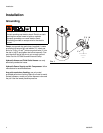
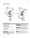
Typical Installation
Key:
A Hydraulic Control, 236864
B Hydraulic Control, 236865
C Hydraulic Return Line
D Hydraulic Outlet, 3/4 npsm (A), 1 1/4 npsm(B)
E Return Line Shutoff Valve
F Hydraulic Inlet, 3/8 npsm (A), 3/4 npsm (B)
G Supply Line Shutoff Valve
H Pressure Gauge
J Pressure Reducing Valve
K Flow Control Valve
L Hydraulic Supply Line (use only Graco hydraulic power
supply)
Hydraulic Fluid Control: The hydraulic fluid control pro-
vides pressure regulation, flow regulation, and pump
isolation. See the Typical Installation as a guide. For
assistance in designing a system to suit your needs,
contact your Graco Representative.
Pressure Regulation:
The hydraulic fluid control pres-
sure reducing valve (J) reduces the hydraulic oil pres-
sure to the operating pressure required for application.
Flow Regulation:
The hydraulic fluid control valve (K)
limits the maximum amount of oil flow to the motor to
keep the hydraulic motor within the recommended cycle
rate limit. This prevents pump runaway. The limit on the
Dyna-Star
™
is 60 cpm. The limit on the Power-Star
™
is
66 cpm.
Pump Isolation:
The hydraulic fluid control (A and B) has
ball valves on the supply and return sides of the mani-
fold. The ball valves isolate the hydraulic fluid control
and pump for servicing without stopping the hydraulic
power source.
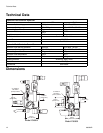
FIG. 2: Typical Installation
L
C
G
E
H
K
A
F
D
J
D
L
C
E
H
B
G
F
K
J
Model 236865
Model 236864