


Operation
308395D 7
Operation
Pressure Relief Procedure
Follow the Pressure Relief Procedure whenever
you see this symbol.
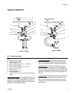
1. Close the supply line shutoff valve (G), and then
return line shutoff valve (E).
2. Hold open the dispensing valve to relieve pressure.
3. Place a container under the drain valve to catch any
drainage. Open the pump outlet drain valve.
4. Leave the drain valve open until you are ready to
pump again.
If you suspect that the dispensing valve nozzle or hose
is completely clogged, or that pressure has not been
fully relieved after following the steps above, VERY
SLOWLY loosen the hose end coupling and relieve pres-
sure gradually then loosen completely, now clear the
obstruction.
Emergency Stop Procedure
Close the red-marked supply line shutoff valve marked
STOP.
Before Starting the Pump
When starting up the hydraulic system, open the return
line shutoff valve (E) first.
Hydraulic Fluid Level Check
Check the hydraulic fluid level in the hydraulic power
supply before each use, and add fluid as necessary to
fill the lines.
Starting the Pump
• Never exceed 1500 psi (10.5 MPa, 105 bar) Maxi-
mum Hydraulic Pressure to the control.
• Never exceed 375 psi (2.6 MPa, 26 bar) Maximum
Outlet Pressure from the control when used with a
1/4:1 Dyna-Star
™
pump.
• Never exceed 1500 psi (10.5 MPa, 105 bar) Maxi-
mum Outlet Pressure from the control when used
with a 1:1 Power-Star
™
pump.
• Be sure all accessories added to the reciprocator
power supply side of the control are capable of at
least 1500 psi (10.5 MPa, 105 bar) maximum work-
ing pressure and all of those for the pump fluid out-
let side of the control have at least 375 psi (2.6 MPa,
26 bar) maximum working pressure for Dyna-Star
™
and 1500 psi (10.5 MPa, 105 bar) for Power-Star
™
.
1. Turn on hydraulic power supply.
2. Open the return line shutoff valve (E) first and slowly
open the hydraulic supply shutoff valve (G).
3. Remove the cap on the pressure reducing valve to
reveal the cap screw adjustment.
4. Adjust the hydraulic inlet pressure from 50 to 1500
psi (0.3 to 10.5 MPa, 3 to 105 bar) with an allen
wrench inserted in the regulator pressure control
adjustment on the pressure reducing valve (J).
Increasing the inlet pressure (clockwise) increases
the pump outlet pressure. Decreasing the inlet pres-
sure (counter clockwise) decreases the pump outlet
pressure.
5. Always use the lowest pressure possible to obtain
the desired results. This reduces pump wear.
This equipment stays pressurized until pressure is
manually relieved. To help prevent serious injury from
pressurized fluid, such as skin injection, splashing
fluid and moving parts, follow the Pressure Relief
Procedure when you stop spraying and before
cleaning, checking, or servicing the equipment.