


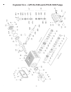
To Disassemble Gear End
1. Loosen inner hexagon screws (49) for the valve casing (43) with an allen wrench. Carefully
remove valve casing from the crankcase (1).
2. Drain oil from the crankcase (1) by removing drain plug (12) with a 3/4" wrench.
3. Loosen inner hexagon screws (10) for the crankcase cover (4) with an allen wrench and remove
crankcase cover.
4. Loosen hexagon screws (17) for the bearing covers (14) with a wrench and remove bearing cover.
5. Loosen connecting rod screws (24) with an allen wrench. Push the stems of the connecting rods as
far as possible into the crosshead guides. Carefully push out the radial shaft seals(31).
Important!!
Connecting rods (24) are marked for identification. Do not twist connecting rod halves.
Connecting rods must be reinstalled in the same position on the crankshaft (22) journals.
6. While slightly turning the crankshaft (22), hit it out carefully to one side with a rubber hammer.
Important!!
Do not bend connecting rod (24) shank.
7. Check the surfaces of the crankshaft (22), connecting rods (24), crosshead assemblies (25) as well
as the radial shaft seals (15 and 31) and taper roller bearings (20).
To Reassemble Gear End
1. Using a soft tool, such as brass or wooden dowel, press in the outer bearing ring until it lines up
with the outer edge of the bearing hole. Assemble the bearing cover (14) together with the shaft
seal (15) and o-ring (16).
2. Fit the crankshaft (22) with pressed-on bearing parts through the bearing hole on the opposite side.
press in outer bearing ring and push it inwards with the bearing cover (14) while keeping the
crankshaft in the vertical position and turning it slowly so that the taper rollers of the bearings touch
the edge of the outer bearing ring.
3. Adjust axial bearing clearance with fitting discs (20A) which are 0.1mm each. The crankshaft (22)
should turn easily with very little clearance. Tighten inner hexagon screws on the connecting rods
(24) to 26 ft.-lbs..
Important!!
There should be enough clearance for the connecting rods (24) to move sideways a little on
the journals.
Important!!
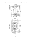
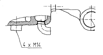
The 1/2” BSP connection in the crankcase serves the purpose of draining leakage water.
The connection should not be closed. See the drawing below.
Repair Instructions - GP5136-5100 and GP5145-5100 Pumps
10