


12
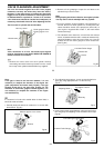
GLOWPLUGS
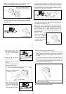
The role of the glowplug
Glowplug life
Particularly in the case of very high performance engines,
glowplugs must be regarded as expendable items.
Install a plug suitable for the engine.
Use fuel containing a moderate percentage of nitromethane
unless more is essential for racing events.
Do not run the engine too lean and do not leave the battery
connected while adjusting the needle.
However, plug life can be extended and engine performance
maintained by careful use, i.e.:
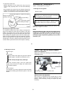
With a glowplug engine, ignition is initiated by the application
of a 1.5-volt power source. When the battery is disconnected,
the heat retained within the combustion chamber remains
sufficient to keep the plug filament glowing, thereby continuing
to keep the engine running. Ignition timing is 'automatic' :
under reduced load, allowing higher rpm, the plug becomes
hotter and, appropriately, fires the fuel/air charge earlier;
conversely, at reduced rpm, the plug becomes cooler and
ignition is retarded.
Apart from when actually burned out, a plug may need to be
replaced because it no longer delivers its best performance,
such as when:
When to replace the glowplug
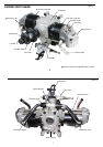
The FT-160 is supplied with an O.S. Type F glowplug,
specially designed for O.S. four-stroke engines.
Foreign matter has adhered to filament or plug body has
corroded.
Engine tends to cut out when idling.
Starting qualities deteriorate.
Filament surface has roughened and turned white.
Filament coil has become distorted.
13
1.5V
1.5V
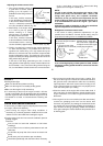
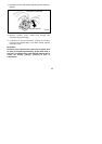
GLOWPLUG HEATING
Glowplug battery
It is necessary to use a glowplug
battery of fairly large capacity (10Ah
or more) as this is required to heat
four glowolugs simultaneously.
A heavy-duty 1.5-volt dry battery or
(preferably) 1.2-volt Ni-Cd battery
may be used.
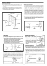
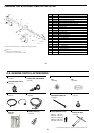
The two glowplug leads supplied with the engine should be
brought together (Fig.13) and connected to a conveniently
located common external point on the fuselage. This can
either be a terminal with a separate terminal for the earth
(ground) lead (Fig.10) or a suitable socket or jack with
connections for both glowplug and earth (ground) leads
(Fig.11) . Note that the earth (ground) lead supplied is much
heavier (2.0 mm multi-strand copper core) than the plug
leads as this has to have the capacity to carry the current for
all two plugs. Similar wire should be used if a single lead is
employed to extend the glowplug leads (Fig.13).
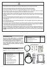
Fig. 9
Heavy-duty dry batteries
A 2-volt lead-acid cell (accumulator) may also be used but
only if porvision is made for reducing the voltage at the plugs
since these are nominally rated at 1.5-volt. See notes below.
Heavy-duty 1.5-volt dry battery
Use at least four heavy-duty cells wired in parallel (Fig.9)
and with short heavy leads (to minimize voltage drop) to the
connection point on the fuselage. The disadvantage of dry
cells is that they cannot be recharged when their power
diminishes and makes the engine difficult to start.
Ni-Cd (nickel-cadmium) 1.2-volt rechargeable battery
Use a 10-Ah cell, or 8 to 10 1.2-Ah cells (as commonly used
for electric-powered R/C cars) wired in parallel and with
short heavy leads (to minimize voltage drop) to the
connection point on the fuselage.
Lead-acid 2-volt rechargeable cell
A lead-acid cell of 10-Ah (preferably greater) capacity is
required. However, in this case, it is necessary to reduce
the applied voltage at the glowplugs to approximately 1.5
volt. The recommended method is to insert a suitable
resistor in each individual plug lead. It is possible, of course,
to use a rheostat attached to the 2-volt cell, or to use extra
long leads (at least 2 metres) to obtain the required voltage
drop. However, the disadvantage of this method is that if
one glowplug should fail or become disconnected, voltage
to the other three will be increased with the risk of burning
out their elements.
Fig.10
Fig.11
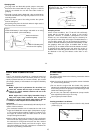
1. Fit terminals to the fuselage.
2. Fit a jack to the fuselage.
2