


7
Installation
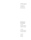
Professional Vent Hoods
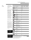
Tools &
Materials
Required
(not supplied)
Wall Mount Installation:
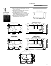
•Six, 5/16" lag screws, 2" long with washers,
all models (provided).
Soffit Installation:
•Six, 5/16" lag screws, 2" long with washers,
all models (provided).
Optional for wall mount installations: (See page 9)
•48" x 18" plywood for 48" model,
36" x 18" plywood for 36" model,
30" x 18" plywood for 30" model.
•Tape measure
•Spirit level
•Wire Cutter
•Wire stripper
•Electric drill
and appropriate bits
•Torx screwdriver
•120V 60Hz 15 or 20 Amp, 2 wire with
ground. Properly grounded branch circuit.
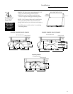
•Metal ductwork, 3-1/4" x 24" or 10" round
for 48" wide model. 7" to 10" round or
3-1/4" x 12" to 3-1/4" x 24" for 30" and 36"
models.
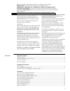
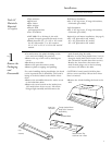
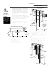
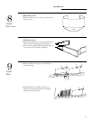
Step
Inner Liner
Disconnect
Through Junction Box on
Rough-In-Kit, Connect to
House Wiring
Remove Screws That
Hold Inner Liner in Place.
To Blower Motor
Hood Inner Liner
Light
Assembly
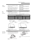
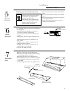
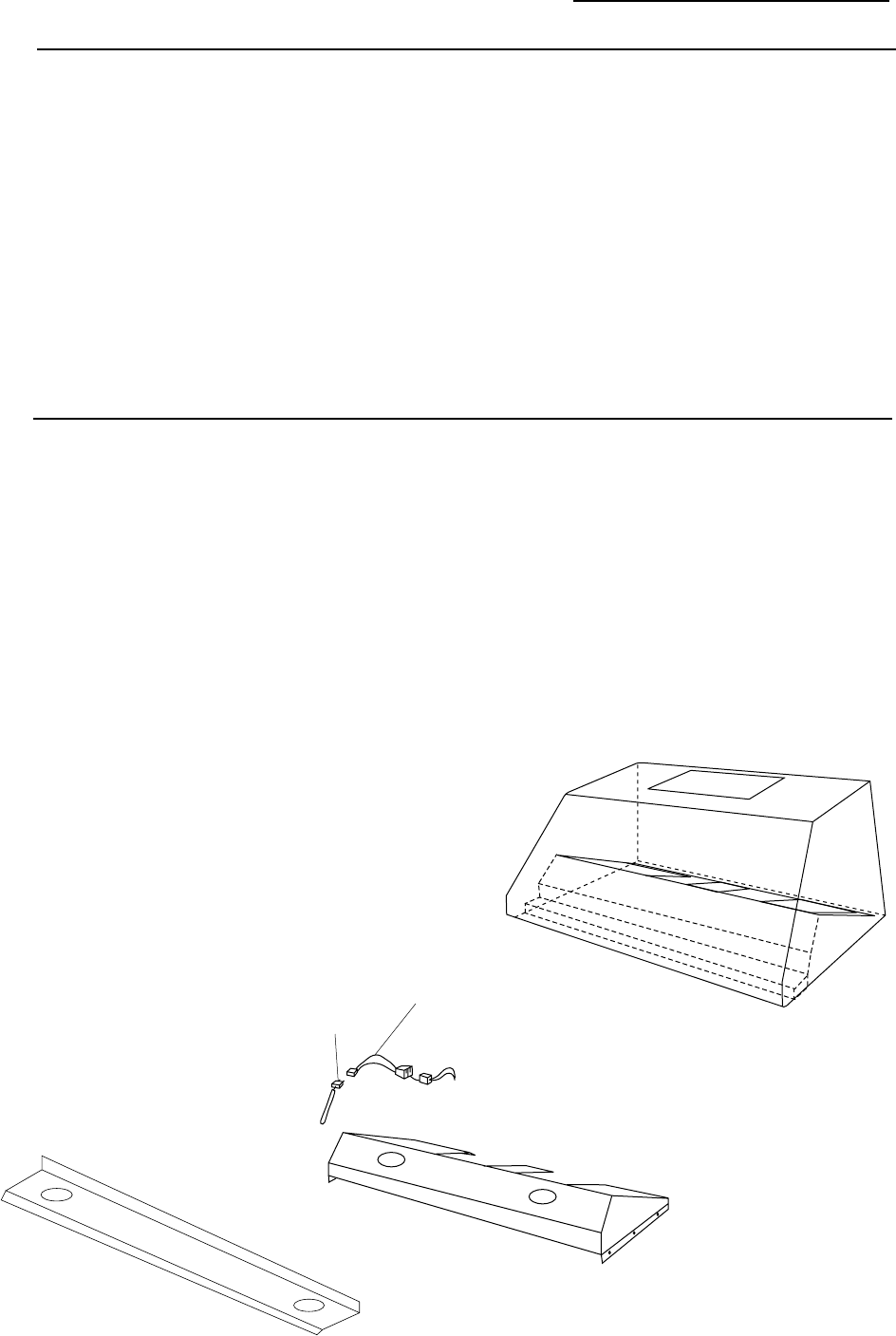
Remove the
Packaging
and
Disassemble
1
•Cut and remove the plastic banding on the
crate and one holding the parts box.
•Remove the top of the crate by backing out
screws.
•Break-away crate sides.
•Remove the parts box and set aside.
•Remove plastic wrapping and padding.
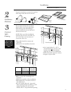
For easier handling during installation, the hood
can be separated into 3 assemblies. The hood is
laying on its back, bolted to the skid in 4 loca-
tions.
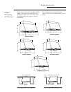
•Remove the assemblies shown for easier access
to the hold-down bolts.
•Remove 8 screws located on the inside front.
(30" models have fewer screws.) Lift off the
halogen light assembly and disconnect the
male/female plug. Set aside.
•Remove 4 screws along inside front, 5 screws
along the inside back and 3 screws on each
side (30 and 36" models have fewer screws).
Remove the inner liner, disconnect the
male/female plugs, one to the heat lamp
and one to the blower. Set aside.
CAUTION: Control panel is held in place
with set screws and may fall out when inner
liner is removed.
•Remove the 4 bolts holding the hood to the
skid.