


Installation
10 Apollo SL30 Installation Manual
3. The valid flag sensitivity shall be 125 mV ± 10% for the flag to leave the stop and
260 mV ± 10% maximum for flag to be fully concealed.
4. The To/From flag shall have an input impedance of 200 ohms ± 10% and a sensitivity
of ± 40 mV ± 15% at 25
o
C with flag fully in view.
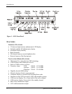
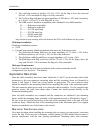
5. The OBS resolver should be compatible with a standard 6-wire OBS interface:
H ...........Reference output high
C............Reference output low
D ...........S1 COS input high
E............S3 COS input low
F ............S4 SIN input high
G ...........S2 SIN input low
Any electrical zero crossing will work because the SL30 will calibrate out any errors.
Glideslope Installation
Glideslope installation requires:
• SL30
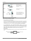
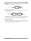
• External non-numeric glideslope indicator that meets the following criteria:
1. The glideslope deviation shall have an input impedance of 1 k ohm ± 10% with a
deflection sensitivity of 150 mV ± 10% for full scale deflection.
2. The glideslope valid flag shall have an input impedance of 1 k ohm ± 10%.
3. The glideslope valid flag sensitivity shall be 125 mV ± 10% for the flag to leave the
stop, and 260 mV ± 10% maximum for flag to be fully concealed.
Helicopter Requirements
The SL30 is qualified for helicopter installation with certain mount tube and SL
configurations (see Section 4 – Limitations).
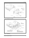
EQUIPMENT MOUNTING
Once the cable assemblies have been made, attach the 15- and 37-pin d-sub and coaxial cable
connectors to the rear connector mounting plate and the mounting frame as illustrated in
Figure 4 and Figure 5. Route the wiring bundle as appropriate. The rear connector plate
should be attached to the mounting frame before installing the frame in the instrument panel.
The rear connector plate can be used to tie down the cable assemblies. Use the supplied edge
guard to protect the cable from sharp edges. Connect the shield grounds directly to the
connector mounting plate.
Once the cable assemblies are complete and the connectors are attached to the mounting
frame, install the mounting frame assembly in the instrument panel as illustrated in Figure 2.
Be sure to use low-profile head screws in the side of the mounting frame so the unit will slide
in and out freely. Attach the front of the mounting frame to the instrument panel. Use support
brackets to attach the rear of the frame to the aircraft.
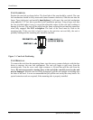
MOUNTING TUBE INSTALLATION
Care must be taken when installing the mounting tube to ensure you can properly insert and
secure the unit. There must be a minimum vertical spacing of 0.040 inches between units to
prevent interference with the cam locking mechanisms. Mounting tubes with clearance