


GPSMAP 400/500 Series Installation Instructions 7
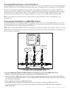
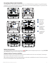
Connecting the Wiring Harness to a NMEA 0183 Device
You can connect the GPSMAP device to other NMEA compatible equipment, such as a DSC or AIS device. Refer to the wiring diagram for
connecting the chartplotter to NMEA 0183-compatible devices.
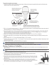
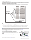
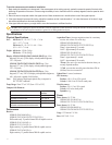
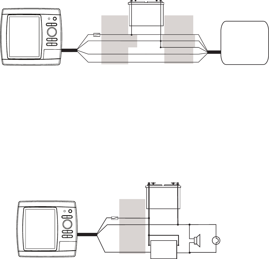
Wiring a GPSMAP 400/500 Series Chartplotter to a Standard NMEA 0183 Device
+
-
>
>
>
>
Red (power)
Black (ground)
Brown (in)
Blue (out)
Wire color
Power
Power ground
NMEA Ground
NMEA Rx/A (+)
NMEA Tx/A (+)
NMEA 0183
compliant device
GPSMAP
400/500
Series
Chartplotter
Battery
10–32 Vdc*
Fuse
3 A
Wire function
To connect the wiring harness to a NMEA 0183 device:
1. For Garmin devices, the ground (black) wires serve as NMEA 0183 ground and must be attached together or on the same terminal as the
NMEA0183groundonyourNMEA0183device.RefertothewiringdiagramofyourNMEA0183deviceforwireidentication.
2. Connecttheblue(NMEA0183port1out)wirefromtheGPSMAP400/500wiringharnesstotheNMEA0183in(orRx/A+)wireonthe
wiringharnessoftheNMEA0183device,andthebrown(NMEA0183port1in)wiretotheNMEAout(orTx/A+)wireonthewiringharness
of the NMEA 0183 device.
3. Repeat step 2 using the grey and violet wires for an additional NMEA 0183 device.
4. Set the serial port(s) on the chartplotter to use NMEA 0183 data (standard or high speed). See the GPSMAP 400/500 Series Owner’s
Manual for more information.
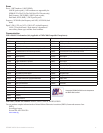
Connecting the Wiring Harness to an Optional Horn, Lamp, or Both
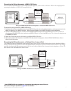
The GPSMAP 400/500 series chartplotter can be used with a lamp, a horn, or both, to sound or ash an alert when the chartplotter displays a
message. The alarm does not need to be wired for the GPSMAP 400/500 chartplotter to function. The alarm circuit switches to a low-voltage
state when the alarm sounds. The maximum current is 100 mA, and a relay is needed to limit the current from the chartplotter to 100 mA. To
select between visual and audible alerts, install a switch.
Wiring a GPSMAP 400/500 Series Chartplotter to a Horn, a Lamp, or Both
+
-
Relay
100 ma max
coil current
Horn
Lamp
GPSMAP
400/500
series
chartplotter
Fuse
3 A
Red
Black (ground)
Yellow (alarm)
Wire color
Battery
10–32 Vdc*
* Certain GPSMAP 400/500 series chartplotters can be connected to higher-voltage power sources. Refer to the
Power section of the System Specications on page 10 for more information.
* Certain GPSMAP 400/500 series chartplotters can be connected to higher-voltage power sources. Refer to the
Power section of the System Specications on page 10 for more information.