


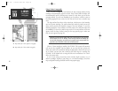
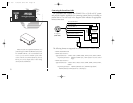
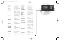
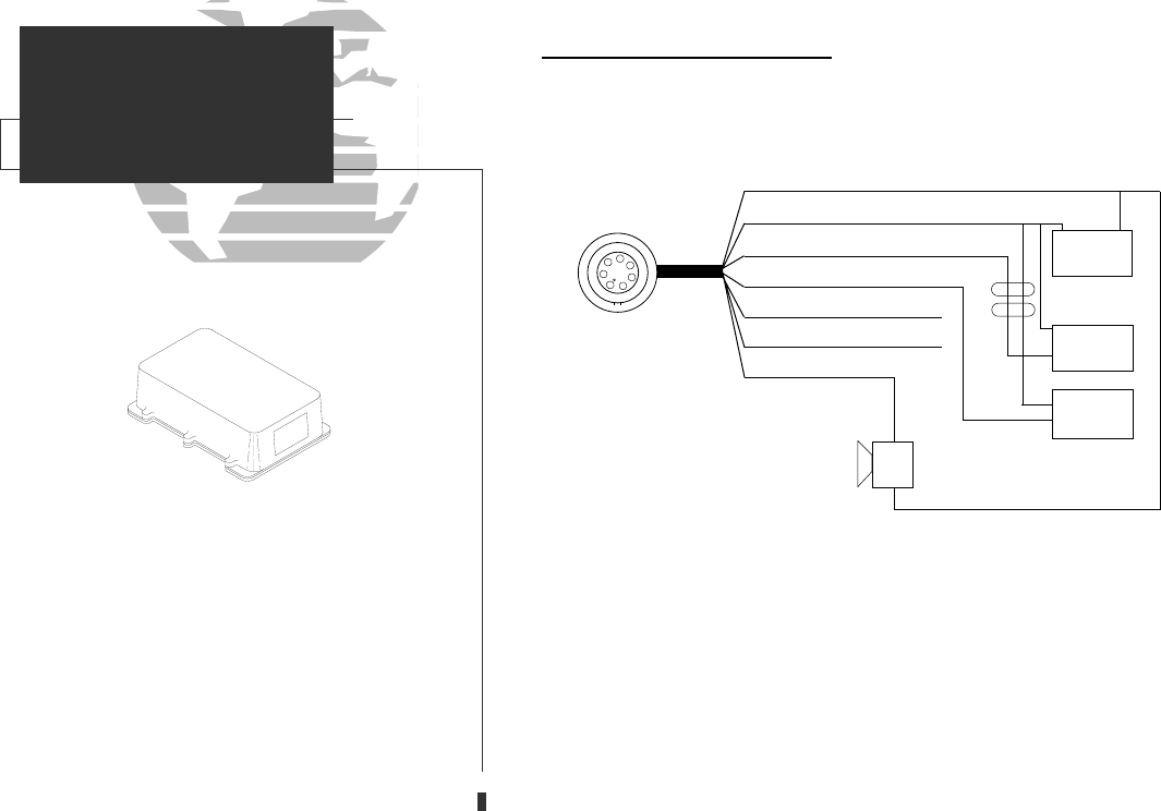
Connecting the Power/Data Cable
The power/data cable connects the GPSMAP 130 to a 10-40 volt DC system
and provides interface capabilities for connecting external devices, including an
external alarm. The color code in the diagram below indicates the appropriate
harness connections.
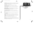
The following formats are supported for connection to up to 3 NMEA devices:
• NMEA 0180/NMEA 0182
• NMEA 0183 version 1.5
Approved sentences—
GPBWC, GPGLL, GPRMB, GPRMC, GPXTE, GPVTG, GPWPL, GPBOD
Proprietary sentences— PGRMM, PGRMZ (alt.), PSLIB (beacon receiver control
input)
• NMEA 0183 version 2.0
Approved sentences—
GPGGA, GPGLL, GPGSA, GPGSV, GPRMB, GPRMC, GPRTE, GPWPL,
GPBOD
Proprietary sentences— PGRME (estimated error), PGRMM (map datum)
PGRMZ (altitude), PSLIB (beacon rec. control input)
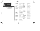
DGPS corrections are accepted in RTCM-104 v. 2.0
format through the NMEA In (BROWN) harness lead.
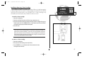
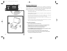
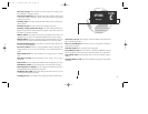
The GARMIN GBR 21 is the recommended beacon
receiver for use with the GPSMAP system.Other
receivers with the correct RTCM format may be used,
but may not correctly display status or allow tuning
control from the GPSMAP unit.
70
GARMIN
GBR 21
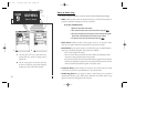
PIN 1 (red): 10-40 volts DC
PIN 2 (black): Ground
PIN 3 (blue): NMEA out
PIN 4 (brown): NMEA in
PIN 5 (white): No connection
PIN 6 (green): No connection
PIN 7 (yellow): alarm low
1
2
3
4
5
6
7
Pin assignment
(CABLE VIEW)
(-) (+)
10-40 volts DC
Autopilot/
NMEA Device
GBR 21
Beacon
Receiver
Alarm/
Relay
(-)
Shield Grounded
Through GPS
(+)
(+)
(-)
(-)
(+)
SECTION
B
APPENDIX
Wiring/Specifications
gps 130 7/23/98 9:23 AM Page 70