


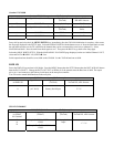

Garmin AT GNS480
Garmin AT GNS480 connections to TruTrak autopilot
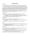
P1 on GNS480 Signal Name (Garmin AT) Signal Name
(TruTrak)
P101 on TruTrak
DII/ADI/ Sorcerer
22 RS232 TxD2 Primary Serial Input 17 / 25
P5 on GNS480 Signal Name (Garmin AT) Signal Name
(TruTrak)
P101 on TruTrak DII
Series
4 429 OUT 1A ARINC-A 14 / 26
24 429 OUT 1B ARINC-B 15 / 27
Power 480 up and select the 1, 4, MENU/ ENTER keys immediately after the GNS 480 initialization is complete. After restart,
the first page displayed is the SETUP page. Select the SERIAL PORTS with the button next to it. Press the small knob to enter
the edit mode and move to the TX column for the channel that you have connected the serial wire to (channel 2). Select
MAPCOM and 9600. Press the small inner knob again to save. Then press the BACK to go back to the Setup page.
Select the ARINC PORTS SETUP. With the MAIN ARINC 429 CONFIG page displayed, on the row labeled Channel 1 OUT,
select and DATA ÎARINC 429, SPEED Î Low.
Serial output baud rate should be set to 9600 on the GNS480. Set the TruTrak baud rate to 9600.
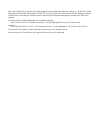
KMD 150
Power the KMD 150 up and turn it full bright. Press the MENU button then the SETUP button then the INST & DIAGS button
then the DATA IN/OUT. Change the DATA OUT PUT to NEMA 0183 the manual states the Baud rate is 9600. The output
pin is pin 11 and connects to the Primary Serial input on the auto pilot controller.
You will need to match 9600 Baud rate in the auto pilot.
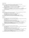
KMD 150 connections to TruTrak autopilot
37 Pin Connector
on KMD 150
Signal Name
Signal Name
(TruTrak)
P101 on
TruTrak DII, ADI/ Sorcerer
11
(AV NAV)
Primary Serial Input
17 / 25
UPSAT GX-50/60/65
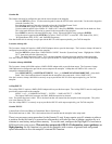
UPSAT GX-50/60/65 connections to TruTrak autopilot
37-Pin Connector
on UPSAT
GX-50/60/65
Signal Name
(UPSAT)
Signal Name
(TruTrak)
P101 on
TruTrak DII, ADI/ Sorcerer
Use pin 5 – TxD1 – if GX has no
GPSS
5
or
22
Use pin 22 – TxD2 – if GX has
GPSS
Primary Serial
Input
17 / 25