


GNC 420/420A Quick Reference
POWER ON
4
190-00140-21 Rev. F
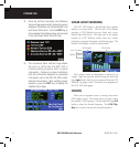
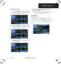
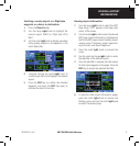
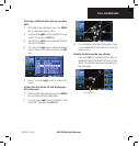
3) Once the self-test concludes, the Database
Versions Page appears which shows the current
database information on the NavData® Card
and Terrain Data cards. Press the ENT Key to
acknowledge the Database Page and proceed
to the Instrument Panel Self-test Page.
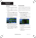
4) The Instrument Panel Self-test Page allows
the pilot to verify that the GNC 420 is
communicating properly with in-panel
instruments. Compare on-screen indications
with the information depicted on connected
instruments, such as the CDI, HSI, RMI, and/or
external annunciators. After verifying proper
operation, press the ENT Key to display the
Satellite Status Page.
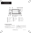
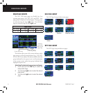
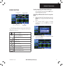
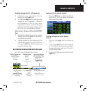
SCREEN LAYOUT (WINDOWS)
The GNC 420’s display is divided into three separate
windows (or screen areas). The left side of the display
provides a COM Window (top two lines) and a user-
defined data field below. The right side of the display
consists of a GPS Window, which shows the various
navigation, waypoint information, and settings pages. The
bottom of the display is used for annunciators.
COM Window
GPS Window
Active Frequency
Standby Frequency
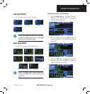
Each unique screen of information is referred to as
a page. Pages are typically selected using the small and
large right knobs, with the cursor removed from the GPS
Window. See pages 6 and 7 for details on arrangement of
the GNC 420’s main pages.
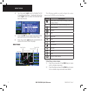
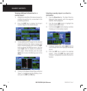
CURSORS
There are two separate cursors: a tuning cursor and a
GPS window cursor. The tuning cursor is used to select
the standby COM frequency. Use the small and large left
knobs to select the desired frequency. The COM Flip-
flop Key is used to activate the selected frequency.