


8
Installation
Connecting the
GBR 23
Connecting the GBR 23 To Your GPS Unit
The final step in installing the GBR 23 is to connect
the receiver’s DATA IN, DATA OUT and GROUND lines
to your GPS unit. The GBR 23 is designed to transmit/
receive data at 4800 baud or BPS (bits per second), which
is suitable for use with all differential-ready GARMIN GPS
receivers and select products made by other manufactur-
ers.
For reliable communication, it is essential that the
GBR 23 and the GPS unit share the same ground. This
ground connection acts as the (current) Return line. It is
recommended to wire the unit to it’s own circuit to avoid
interference from other electronics.
Some non-GARMIN GPS units may have a separate
data line labeled “RETURN”, “DATA GROUND” or “DATA
-”. If one of these lines exist, connect the BLACK wire
from the power/data cable to it.
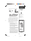
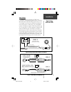
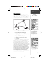
1. You may reference Figure 3 for the following wiring:
Connect the BLUE (Data Out) wire from the GBR
23’s power/data cable to the DATA INPUT line of
the GPS unit.
2. Connect the BROWN (Data In) wire to the DATA
OUTPUT line of the GPS unit.
3. Connect the BLACK (-) wire to the GROUND wire of
the GPS unit. If the BLACK wire is already connected
to the same ground terminal as the GPS unit, no
additional connection is required (unless a separate
RETURN line is provided by the GPS unit).
4. Connect the RED (+) wire from the power/data
cable to a 8-35 vDC power source. It is advisable to
use a slow response fuse or circuit breaker in the
range of 2A to 6A to protect the curcuit.
5. If a remote power switch is being installed, see
Figure 2. This will allow the GBR 23 to remain
connected to a power source, but manually
powered on and off. If the receiver is being wired to
a circuit which is already switched, (with the GPS
for example) connect the WHITE wire to ground or
the same location as the BLACK wire. When the
BLACK and WHITE wires are combined, the GBR 23
will turn on/off when power is applied/removed to
the RED (+) and BLACK (-) wires.
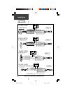
You may also output corrected
NMEA data from a GARMIN GPS/
DGPS combination to a PC or
another NMEA device (autopilot,
radar, chartplotter, etc.). GARMIN
GPS units can support NMEA data
output for up to three devices (the
GBR 23 counts as one). Most
NMEA device configurations only
require that the GROUND (-) and
the DATA OUT (+) wires from the
GPS (which are also connected to
the GROUND (-) and DATA IN (+)
wires of the GBR 23) to be
connected. Please refer to the
instructions or manufacturer of the
NMEA device for correct wiring
procedures.
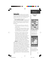
PC Connections
Connect the harness leads
from the GPS to a 9-pin serial
connector:
Data Out From GPS - Pin 2
Data In From GPS - Pin 3
Ground From GPS - Pin 5
*
1
2
3
45
67
9
8
* When wiring a GARMIN GPS/
DGPS combination, connecting the
DATA OUT from the PC (pin 3) to
the DATA IN of the GPS will
disable the DGPS (since the GPS
only allows for one input). If you
need to upload/download data
between the GPS and PC, it is
advisable to install a switch which
toggles the input to the GPS
between the DGPS or PC.
GBR 23 Manual.p65 5/23/00, 1:28 PM8