


8
INSTALLATION INSTRUCTIONS
GPSMAP 2106/2110 & GPS 17
Power/Data Cable Wiring
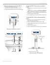
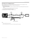
The following pages contain several wiring diagrams. The first diagram on the next page is a simple diagram showing the GPSMAP 2106/2110
MFD using the 18-pin Power/Data wiring harness and the GPS 17. If two GPSMAP 2106/2110 units are installed and connected, only one
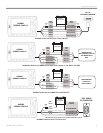
GPS 17 antenna needs to be installed. Next are wiring diagram examples showing the GPSMAP 2106/2110 using the 18-pin Power/Data
wiring harness interfacing with a variety of different equipment. Refer to the wiring diagram that best suits your needs. For third-party devices,
refer to the wiring guidelines included with that equipment. Use 22 AWG (18 AWG for the Red and Black wires), shielded, twisted-pair wiring
for extended runs of wire. Solder all connections and seal the connection with heat shrink tubing. If networking two MFDs, the GPS 17 and
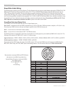
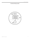
NMEA input devices should only be attached to one MFD. A pinout of the cable is shown below.
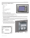
Power/Data Cable Input/Output Ports
The GPSMAP 2106/2110 Power/Data cable has four I/O (Input/Output) ports.
Ports 1 and 2—communicate with other NMEA-compliant devices, such as VHF radios, NMEA instruments, autopilots, or PCs (Port 1 only).
You can input one NMEA device to each port, and output in parallel to three NMEA devices per port.
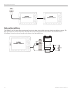
Port 3—is reserved for use with Garmin sounder modules.
Port 4—is reserved for use with the Garmin GPS 17 GPS/WAAS antenna.
The following formats are supported for connection of external devices: Garmin proprietary sonar module and NMEA 0183 version 3.01. The
following are the sentences for NMEA 0183, version 3.01 and later output:
Approved sentences—GPBWC, GPRMC, GPGGA, GPGSA, GPGSV, GPGLL, GPBOD, GPRMB, GPRTE, GPVTG, GPWPL, and GPXTE.
Garmin proprietary sentences
—PGRME, PGRMM, PGRMZ, and PSLIB.
The unit also includes NMEA input with support for the WPL sentence, DSC, and sonar NMEA input with support for the DPT (Depth) or
DBT, MTW (Water Temp), and VHW (Water, Speed, and Heading) sentences. The unit interface must be set to NMEA In/NMEA Out
.
Documentation concerning NMEA and RTCM formats
and sentences are available for purchase from:
National Marine Electronics Association (NMEA)
Seven Riggs Avenue
Severna Park, MD 21146
U.S.A.
www.nmea.org
PIN # COLOR FUNCTION
1 N/C
2 N/C
3 N/C
4 WHITE/BROWN PORT 3 DATA IN
5 WHITE/BLUE PORT 3 DATA OUT
6 ORANGE ACCESSORY ON
7 N/C
8 N/C
9 VIOLET PORT 2 DATA IN
10 GRAY PORT 2 DATA OUT
11 YELLOW ALARM LOW
12 N/C
13 WHITE PORT 4 DATA IN
14 GREEN PORT 4 DATA OUT
15 RED DC POWER INPUT
16 BROWN PORT 1 DATA IN
17 BLUE PORT 1 DATA OUT
18 BLACK GROUND (POWER/DATA)
2
15
18
11 10
6
5
17
16
14 13
12
1
9
4 3
8
7
Cable End View