


8
INSTALLATION INSTRUCTIONS
GPSMAP 2006C/2010C & GPS 17
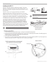
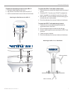
Wiring
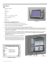
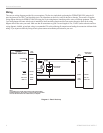
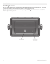
There are two wiring diagrams provided for you convenience. The first is a simple hook-up showing the GPSMAP 2006/2010 (using the 18-
pin wiring harness), the GPS 17 and the alarm circuit. The Alarm does not have to be wired for the unit to function. The second is a complete
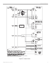
wiring diagram showing the GPSMAP 2006/2010 (using the 18-pin wiring harness) interfacing with a variety of different equipment. The extra
5-pin wiring harness that came with the unit is intended for future interfacing features and does not require connection. Refer to the wiring
diagram that will best suite your needs. Make sure that all connections are good. For extra lengths of wire, 24 AWG (unless otherwise noted on
wiring diagram), shielded, twisted-pair wiring is recommended. We advise soldering all connections and sealing the connection with heat shrink
tubing. If you experience difficulty wiring the unit, please contact an installation professional in your area.
WIRE
COLOR
WIRE
COLOR
18 AWG
18 AWG
1 A
5 A
ALARM
SEE NOTE
GARMIN GPS 17
GPS SENSOR
BLACK
GROUND
YELLOW
ON
RED
POWER
BLUE
WHITE
YELLOW
ALARM
GROUND BLACK
PORT 4 OUT GREEN
ACCESSORY ON ORANGE
DC INPUT RED
PORT 4 IN WHITE
COM 1 IN
COM 1 OUT
SHIP'S BATTERY
10-32 VOLTS
GARMIN
GPSMAP 2006/2010
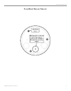
NOTE:
THE ALARM OUTPUT CAN BE USED TO DRIVE ALAMP, HORN, OR BOTH.
MAXIMUM CURRENT IS 100 MILLIAMPS. A SWITCH OR RELAY CAN BE USED
TO SELECT BETWEEN VISUALAND AUDIBLEALERTS, IF REQUIRED
+
-
Diagram 1 - Basic Hook-up