


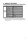

5
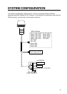
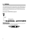
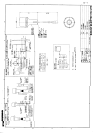
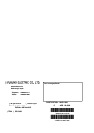
Connecting to FURUNO Multi Display RD-30
10 m
w/cable
MULTI DISPLAY
RD-30
AUX port
IN/OUT port
12-24 VDC
AUX
IN/OUT
12-24
VDC
Rear Panel
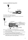
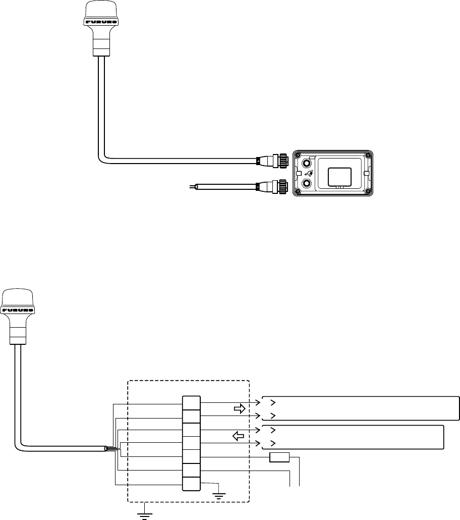
Connecting to other type of equipment
Cut the connector and fabricate the cable end, using a crimp-on lug similar terminal.
Prepare a junction box locally.
10 m
w/cable
non-NAVnet
RS-422* input for radar/plotter
RS-422 output from GR-80
NMEA0183 Ver.2.00
*: RS-422 output can be received by current loop.
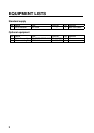
1
2
3
4
5
6
7
WHITE
BLACK
YELLOW
JUNCTION BOX
GREEN
RED
BLUE
Drain Wire
1
2
3
4
RD-A
RD-B
TD-A
TD-B
Fuse 0.5A
12-24 VDC (ship's battery)
(Input current: 105-55 mA)
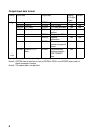
Note1) Maximum input voltage is 31.2 VDC. Voltage higher than that will damage the
antenna. To connect battery of over 31.2 VDC, contact your dealer to request
connection of external circuit.
Note2) When connecting a FURUNO external DGPS beacon receiver (such as the GR-80)
to this unit, set the external DGPS beacon receiver as follows:
Byte Format, 8-6; First Bit, LSB; Parity Bit, None; Stop Bit, 1; Bit Rate, 8.
Note3) The signal ground and frame ground are separated, however the power line is not
isolated. Therefore, do not connect the signal ground to the frame ground when
connecting other equipment to a positive ground battery.