


Antenna Radiators
1. Type Slotted waveguide array
2. Beamwidth and sidelobe attenuation
3. Rotation
RF Transceiver
1. Frequency
X-band: 9410 MHz ±30 MHz
S-band: 3050 MHz ±30 MHz
2. Output power
3. Pulselength/PRR
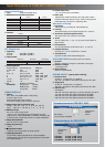
Range scale (nm)
Pulselength (µs) PRR (Hz)
0.125, 0.25 0.07 3000
0.5 0.07, 0.15 3000
0.75, 1.5 0.07, 0.15, 0.3 3000, 1500
3 0.15, 0.3, 0.5, 0.7 3000, 1500, 1000
6 0.3, 0.5, 0.7, 1.2 1500, 1000, 600
12, 24 0.5, 0.7, 1.2 1000, 600
48, 96 1.2 600
4. I.F. 60 MHz, Logarithmic
Bandwidth Short pulse: 40 MHz
Middle pulse: 10 MHz
Long pulse: 3 MHz
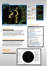
RADAR DISPLAY
1. Display
23.1" color LCD (SXGA 1280 x 1024 pixels),
470 (H) x 353 (V) mm,
Effective display diameter: 340 mm
Echo Color: Yellow, green or white in 32 levels
2. Range scales and ring intervals (nm)
Range: .125, .25, .5, .75, 1.5, 3, 6, 12, 24, 48, 96
Ring: .025, .05, .1, .25, .25, .5, 1, 2, 4, 8, 16
3. Minimum range
30* m on 0.75 nm range scale
*Using a 10 m
2
test target at 3.5 m high above sea and
antenna at 15 m high (IEC 60936-1). Different conditions give
a different result, maybe close to 20 m in actual installations.
4. Range discrimination
30 m on 0.75* nm range scale
5. Range ring accuracy
+
0.2 %
6. Presentation modes
Head-Up, Course-Up, North-Up, North-Up TM
7. Heading information
Furuno GPS compass SC-60/120 is a recommendable
heading sensor as a backup of a gyrocompass. Confirm with
your Administrations.
8. Parallel index lines
1, 2, 3 or 6 lines (menu selectable)
9. Radar map
1500 points to create coastlines, own ship safety contour,
isolated underwater dangers, buoys, traffic routing systems,
prohibited areas, fairways as required by IMO.
Automatic Plotting
1. Acquisition
100 targets (e.g. manually 50, automatically 50)
2. Tracking
Automatic tracking of all acquired targets in 0.1 to 32 nm
3. Guard zone (Target Acquisition Area)
Two guard zone, one of them 0.5 nm depth
4. Vector
True or relative 30 s, 1, 3, 6, 12, 15, 30 min for prediction of
target motion
5. Past positions
5 or 10 past positions at intervals of 30 s,1, 2, 3, 6 min.
6. Collision warning
CPA limit: 0.2 - 10 nm, TCPA limit: 0 - 99 min.
7. Trial maneuver
Dynamic or static, with selected delay time.
AIS FUNCTIONS (Data input from AIS is required)
1. Symbols
Sleeping, Activated, Dangerous, Selected, Lost targets
2. Number of targets
1,000 targets max.
3. Data indication
Basic and expanded data
POWER SUPPLY (specify when ordering)
1. Processor Unit
24 VDC or 115/230 VAC, 1ø, 50/60 Hz
440 VAC, 1ø, 50/60 Hz with optional transformer RU-1803
2. Display Unit
24 VDC or 115/230 VAC, 1ø, 50/60 Hz
440 VAC, 1ø, 50/60 Hz with optional transformer RU-1803
3. Antenna Unit
FAR-2837S:
230 VAC, 3ø, 60 Hz; 380 VAC, 3ø, 50 Hz; 440 VAC, 3ø, 60 Hz
115 VAC, 3ø, 60 Hz with optional transformer RU-5693
230 VAC, 3ø, 50 Hz with optional transformer RU-6522
440 VAC, 3ø, 50 Hz with optional transformer RU-5466-1
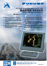
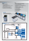
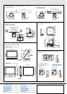
Specifications of
FAR-2817/2827/2837S
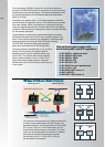
8 ft antenna
(4 or 6.5 ft also available)
Performance
Monitor
built in
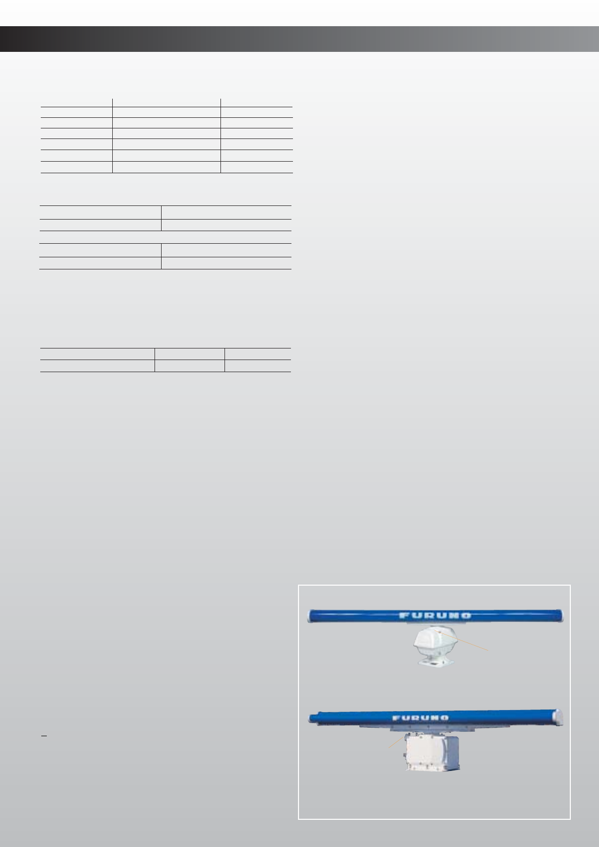
S-band antenna for FAR-2837S
Performance
Monitor
built in
X-band antenna for FAR-2817, 2827
FAR-2817: X-band, 12 kW, TR up
FAR-2827: X-band, 25 kW, TR up
FAR-2837S: S-band, 30 kW, TR up
X-Band
S-Band
Rotation
Gear Box
Rotation
Gear Box
24 rpm
RSB-096
42 rpm
RSB-097
RSB-098 RSB-099 RSB-100
45 rpm
RSB-101 RSB-102
21/26 rpm
X-Band
S-Band
Radiator Type
Length
Beamwidth(H)
Beamwidth(W)
Sidelobe
(within ± 10°)
Sidelobe (outside ± 10°)
XN-12AF
4 ft
1.9°
20°
-24 dB
-30 dB
XN-20AF
6.5 ft
1.23°
20°
-28 dB
-32 dB
XN-24AF
8 ft
0.95°
20°
-28 dB
-32 dB
SN-30AF
10 ft
2.3°
25°
-24 dB
-30 dB
S-band 10 ft radiator usable for an HSC
SN-36AF
12 ft
1.8°
25°
-24 dB
-30 dB
Output Power
Transceiver
FAR-2817
12 kW
RTR-078
FAR-2827
25 kW
RTR-079
FAR-2837S
30 kW
RTR-080