


1. INSTALLATION
1-10
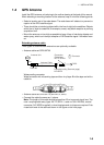
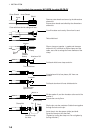
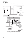
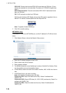
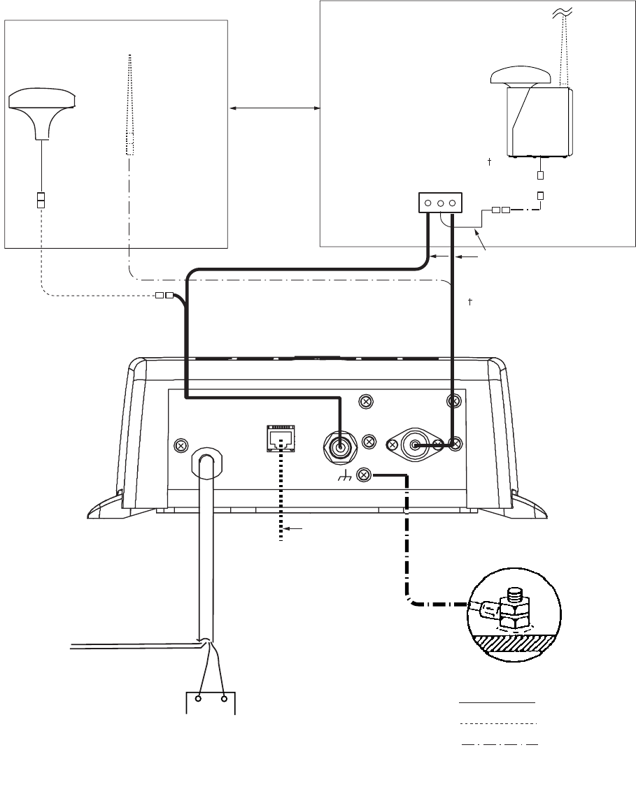
1.7 Wiring
Connect power source, LAN cable, VHF antenna and ground wire as shown below.
RED BLACK
PC, HUB,
NAVNET
GROUND
GROUND WIRE
IV-1.25sq
LAN CABLE
P5E-4PTX-BL
(2 m or 10 m)
AIS TRANSPONDER
POWER CABLE
(supplied)
12-24 VDC*1
RS-422 RATING*2
Switchboard breaker
+
-
: Standard
: Option
: Local Supply
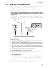
GPS Antenna
GPA-017/S
150M-W2VN
Either one
RG-10U/Y, 50 m
RG-10U/Y (8D-FB-CV,
option)
Attached to Distributor
(approx. 1m)
Distributor
DB-1
GPS/VHF Combined
Antenna GVA-100-T
8D-FB-CV, 30 m/50 m: Option
RG-10U/Y, 20 m: Local supply
0.6 m
0.8 m
: Ground is not required.
*1: Supply from breaker on switchboard.
*2: If COM lines (connection for NavNet, sensor) are not used,
tape them to prevent short circuit.
NETWORK
VHF ANT
COM/POWER
12-24 VDC
2.0-1.0 A
GPS ANT