


bed bolts) apply Loctite®, reinstall bolt and
tighten to vehicle manufacturer torque
specifications.
24. Connect the steering shaft to the steering
extension. It will only go on one way. Be sure
that the steering shaft and the steering wheel
have not turned from their original location.
Install the stock steering bolt in the steering
shaft. Be sure that the bolt engages the slot on
the steering extension.
25. Bolt the transfer-case-lever extension
bracket to the transfer-case-lever using two
5/16" x 1 1/4" bolts, four 5/16" SAE washers,
and two 5/16" nylock nuts, and reinstall the
shift lever to the transfer-case shift linkage
using the stock hardware. Check the shift
lever operation. Be sure that it engages
properly in all 4-wheel drive ranges. Install the
mounting bolt and tighten it securely. Mount
the inner shift boot to the floorboard. Tighten
the mounting screws securely. Mount the
outer shift boot to the inner housing. Tighten
the mounting screws securely. Check the shift
lever operation once more.
26. Mount the parking-brake cable relocating-
bracket to the parking brake cable hole in the
cab mount using a 5/16" x 1" bolts, two 5/16"
USS washers and one 5/16" nylock nut. Route
the front parking brake cable through the
largest hole in the relocating bracket.
Reconnect the front cable to the rear cable at
the clip. Adjust the parking brake cable to
factory specifications. Set parking brake to
help prevent the vehicle from rolling.
27. Replace the carpeting to its original
location. Reinstall both kick panels and both
doorjamb scuff plates. On supercab models,
replace the rear seat at this time. Mount the
seat on the studs protruding from the
floorboard. Install the bolts into the floorboard.
Install the nuts onto the studs. Tighten all
mounting hardware securely.
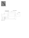
28. The fan shroud needs to have two
notches cut into the bottom. The notch for the
drain is 4" high and 3 1/2" wide. The notch for
the lower radiator hose is 4" high and 7" wide.
The shroud should be placed on the radiator
to mark the locations for the notches. The
shroud should resemble the picture. Pace the
fan shroud over the fan, then reinstall the
radiator in the vehicle. Reconnect both
radiator hoses. Reinstall the top mounting
bolts and cover. Be sure that all hose clamps
and lines are tightened properly and that the
drain is completely closed. Refill the radiator. It
will need to be topped off when the vehicle is
started. Using the stock bolts mount the two
upper fan shroud lowering brackets to the
radiator where the fan shroud was originally
mounted. Do not tighten. Mount the fan shroud
to the studs protruding from the fan shroud
brackets. Install a 1/4" washer and nylock nut
on each stud. Do not tighten. Check the fan to
fan-shroud clearance. Be sure that the gap is
the same all the way around the fan. Tighten
the upper mounting hardware and secure the
bottom of the shroud to the core support using
the supplied zip ties. Replace the air intake
duct to the top of the throttle body. Reconnect
the duct to the air filter housing. Close the
clamp at the air filter housing. Tighten the
clamp at the throttle body. Reinstall the cover
over the throttle body. Tighten the mounting
bolts securely.
29. Lengthen the fuel filler hose. Mark the
hose just below the bend so the two pieces
can be properly aligned after the extension
has been installed. Cut the filler pipe into two
pieces. Remove all burs and shavings from
the pieces of the hose. Install the round fuel
filler extension between the two pieces of the
filler hose. Install a #28 hose clamp at each
end of the filler extension. Tighten both hose
clamps securely. Remove the fuel vent hose.
Install the longer vent hose provided with the
kit. Install a #10 hose clamp on the new vent
hose and tighten securely. Reinstall the fuel
filler assembly on the vehicle. Install the fuel
filler hose to the fuel tank using the stock hose
clamp. Install the vent hose to the fuel tank
using the remaining #10 hose clamp. Mount
the filler neck to the body using the stock
screws. Be sure that the filler hose engages
properly at all areas. Tighten all fuel filler
hardware securely. Reinstall the fuel filler cap.
30. Install the front bumper. The bumper will
need to be notched along the bottom edge to
clear the front spring hanger. Use the drawing
to properly locate the notches. The drawing
shows the passenger side cutout, the drivers
side cutouts are a mirror image of the drawing.
Using eight 7/16" x 1" bolt, eight 3/8” washers,
eight 7/16" washers and eight 7/16" nylock
nuts, bolt the relocation brackets to the
bumper. Do not tighten. Using four 7/16" x 1
1/2" bolt, eight 7/16" washers and four 7/16"
nylock nuts, bolt the bumper to the frame.
Adjust the bumper to body clearance using the
dimensions recorded earlier. Tighten all
bumper mounting hardware securely.
Reconnect any wires that were previously
disconnected from the front bumper. Replace
the rubber air flap to its original location.
31. Install the rear bumper. Mount the
relocating brackets to the rear bumper using
the stock hardware. Mount the bumper