


Automotive Application Example
The following is an application example of how to measure a DIS
system (with dual-spark ignition coils) for a 4-cylinder engine. See
Figure 3.
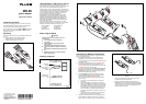
Test Tool Key Sequence
Q
R
S
T
U
Connect the DIS 90, the Capacitive Secondary Pickup, and
the ground leads as displayed on the Fluke 98 and depicted in
the example of Figure 3.
V
Starts the secondary parade measurement.
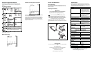
Start the engine and observe the measurement result. See an
example display in Figure 5.
Measurement Result
Figure 5. Typical Result Screen
Indication of wrong polarity connections
Figure 6. One red (positive) and one black (negative) secondary
pickup swapped (4-cylinder system).
If you connect a pickup to a cable with the wrong polarity, the
ignition pulses of the related cylinder are displayed upside down
and the RPM display is not correct. In the example of Figure 6,
where two out of four pickups are wrongly connected, the RPM
display is half the real value.
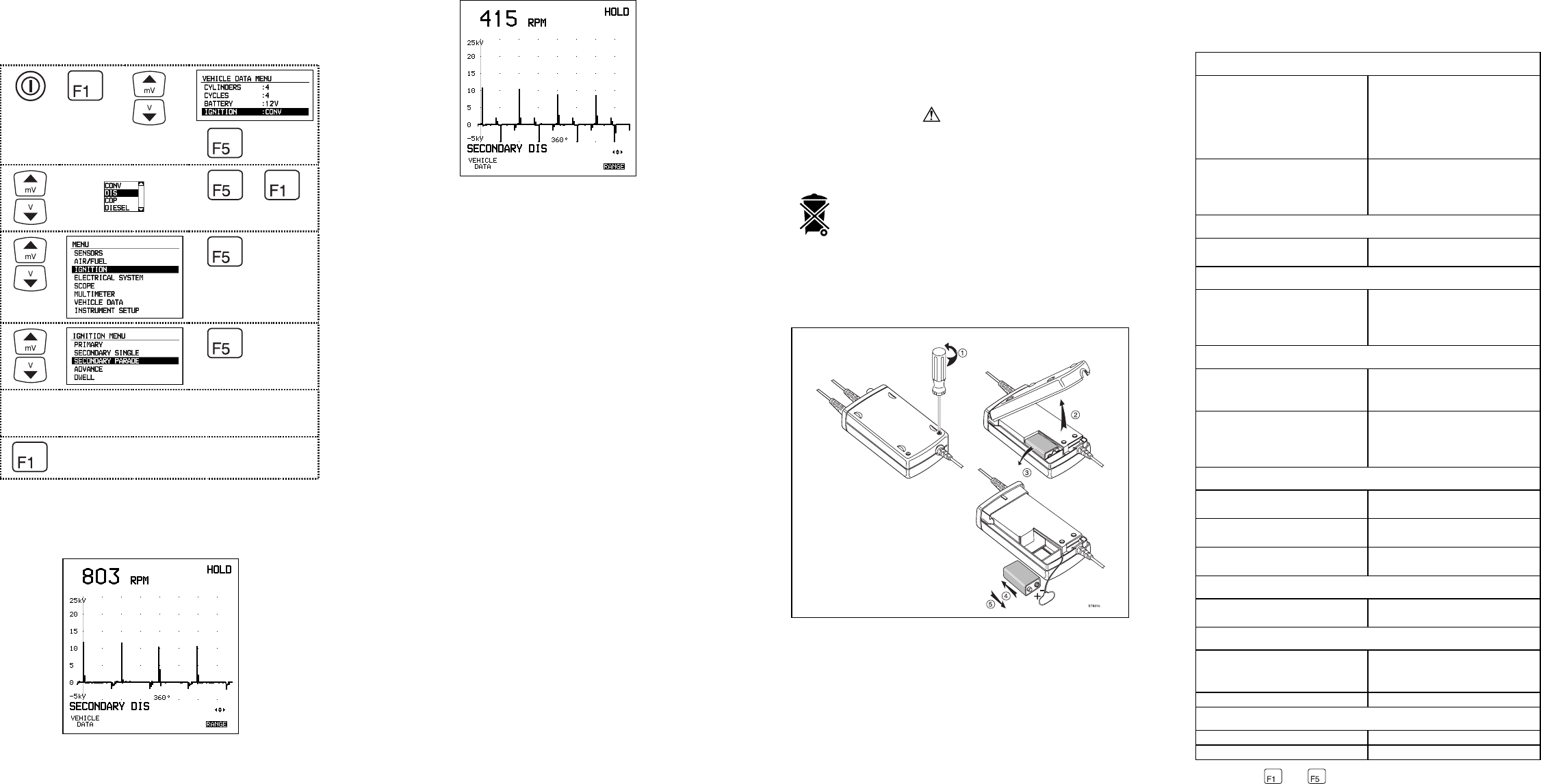
Service and Maintenance
Storing the DIS 90
If you are storing the DIS 90 for an extended period of time, the
battery should be removed and stored separately. To remove the
battery, see Figure 7.
Replacing the 9V Battery
Warning
To avoid electrical shock, disconnect the DIS 90 from
the ignition cables before replacing the battery.
Note:
This instrument contains an alkaline battery. Do not
dispose of this battery with other solid waste. Used
batteries should be disposed of by a qualified recycler or
hazardous materials handler. Contact your authorized
FLUKE Service Center for recycling information.
Replace the 9V battery when the ‘BATTERY OK’ LED on the
IGNITION ADAPTER unit remains off when the power is switched
on.
Service Centers
To locate an authorized service center, visit us on the World Wide
Web:
http://www.fluke.com
or call Fluke using any of the phone numbers listed below:
+1-800-443-5853 in U.S.A. and Canada
+31-402-678-200 in Europe
+1-425-356-5500 from other countries
Specifications
FLUKE guarantees the properties expressed in numerical values
with the stated tolerance. Specified non-tolerance numerical values
indicate those that could be nominally expected from the mean of a
range of identical differential voltage probes.
GENERAL
DIS 90 application Parade measurement on
Distributorless Ignition Systems
with the Fluke 98 Automotive
ScopeMeter Series II, Version
2.70 and higher (see the note at
the bottom)
Maximum number of cylinders 8
4 positive igntion voltages (red
pickup clamps) and 4 negative
(black pickup clamps)
TRIGGER INPUT
Trigger input device to be
used
Secondary Pickup CAP90-2 or
PM9096/101 (Europe only).
TRIGGER OUTPUT
Connection to the Fluke 98 Dual banana plug (on small
box). Black plug to COM input,
red plug to TRIGGER input on
the Fluke 98.
SIGNAL OUTPUT
Connection to the Fluke 98 Red BNC connector (safe
model). Connected to INPUT A
on the Fluke 98.
RPM range:
4-cylinder engine
6-cylinder engine
8-cylinder engine
600 to 8000 RPM
600 to 6000 RPM
600 to 4500 RPM
CABLE LENGTHS
Secondary Pickup cable (from
clamp to splitter box)
0.85 m
From splitter box to adapter
box (connected)
2 m
From adapter box to Fluke 98
(connected)
0.5 m
IGNITION ADAPTER
Box dimensions (length x
width x height)
90 x 25 x 40 mm
BATTERY
Battery requirement Type 6 LR 61,
9V Alkaline NEDA 1064,
IEC6F22.
Battery life 100 hours
ENVIRONMENTAL
Temperature operating 0 to +50 ºC
Temperature non-operating -40 to +70 ºC
Note: Press
and simultaneously to read the version
number. Please contact your local representative for
information about upgrading the version.
Figure 7. Replacing the Battery