®
DIS 90
Ignition Adapter
Instruction Sheet
Introducing the DIS 90
The DIS 90 is an optional accessory for use with the Fluke 98
Automotive ScopeMeter
®
Series II, Version 2.70 and higher, to
measure parade on Distributorless Ignition Systems.
To check the version number press
and simultaneously.
Please contact your local representative for information about
upgrading the version.
Unpacking
Check that the following items are included with the DIS 90 (see
Figure 1):
•
Ignition Adapter Unit with installed 9V battery
•
Secondary Pickup Set with 4 black clamps
•
Secondary Pickup Set with 4 red clamps
LIMITED WARRANTY & LIMITATION OF LIABILITY
This Fluke product will be free from defects in material and
workmanship for one year from the date of purchase. This warranty
does not cover fuses, disposable batteries or damage from
accident, neglect, misuse or abnormal conditions of operation or
handling. Resellers are not authorized to extend any other warranty
on Fluke’s behalf. To obtain service during the warranty period,
send your defective product to the nearest Fluke Authorized
Service Center with a description of the problem.
THIS WARRANTY IS YOUR ONLY REMEDY. NO OTHER
WARRANTIES, SUCH AS FITNESS FOR A PARTICULAR
PURPOSE, ARE EXPRESSED OR IMPLIED. FLUKE IS NOT
LIABLE FOR ANY SPECIAL, INDIRECT, INCIDENTAL OR
CONSEQUENTIAL DAMAGES OR LOSSES, ARISING FROM
ANY CAUSE OR THEORY.
Since some states or countries do not allow the exclusion or
limitation of an implied warranty or of incidental or consequential
damages, this limitation of liability may not apply to you.
Fluke Corporation Fluke Industrial B.V.
P.O. Box 9090 P.O. Box 680
Everett WA 7600 AR Almelo
98206-9090, USA The Netherlands
Safely using the DIS 90
Warning
Do the following to avoid electrical shock, fire, or
personal injury:
•
Turn the engine off before making any
connections.
•
Use the DIS 90 only on properly insulated
ignition cables.
•
Keep the Fluke 98 and the DIS 90 leads away
from rotating parts and engine parts producing
heat.
•
Thoroughly fix all test leads before doing a road
test.
•
Read the safety section in the Fluke 98 Users
Manual (from page VI).
Powering the DIS 90
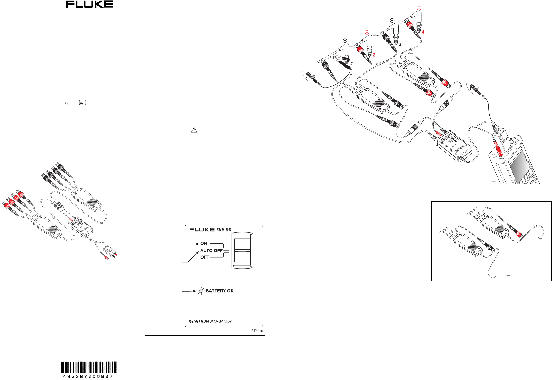
Connecting the DIS 90 for measurement
Figure 3 shows a connection example for a 4-cylinder DIS engine.
General connection procedure:
1. Connect the DIS 90 Adapter to the Fluke 98 Automotive
ScopeMeter as shown in Figure 3. Use a ground lead to
connect the COM input on the small connection unit to ground
e.g. battery ground.
2. Connect the round cable plug of the
red
secondary pickup
set
to the Ignition Adapter box on the input with the
red
grommet
(connection to the input with the black grommet will
not fit because of different plug pinning!)).
3. Connect the round cable plug of the
black secondary pickup
set
to the Ignition Adapter box on the input with the
black
grommet.
(Connection to the input with the red grommet will
not fit because of different plug pinning!)
4. Connect the
black
secondary pickup clamps to the spark
leads with
negative
polarity and the
red
secondary pickup
clamps to the spark leads with
positive
polarity.
You can check the polarities as follows (only possible with
engine running):
a. Use a black or red secondary pickup and clamp it to a
spark lead.
b. If the Fluke 98 displays an upward spark voltage, this
pickup is connected to the correct polarity. If a downward
spark voltage is displayed, the pickup is connected to the
wrong polarity. Then use a pickup with the other color for
this cylinder. Bear in mind that the spark voltage may be
low or not visible due to a defect. Refer to the section
“Indication of wrong polarity connections” on the back of
this sheet.
c. Use the next black or red secondary pickup and repeat
steps a and b until all pickups are connected.
6. Clamp the remaining pickups on the connecting cable to the
Ignition Adapter unit. See the example for four cylinders in
Figure 3 and for six cylinders in Figure 4. For safety reasons
and to get a reliable measurement result, these unused
pickups must not be left unconnected.
7. Clamp the Capacitive Secondary Pickup (CAP 90 or
PM9096/001) on a spark lead with negative polarity (
black
pickup connected). Clamp it as close as possible to the spark
plug (see figure 4). This cylinder is then displayed as first
cylinder in the parade picture.
Figure 3. Measurement setup with the DIS 90 for a 4-cylinder dual-spark ignition coil system.
Figure 1. DIS 90 Package Contents
Figure 4. Connection of the unused pickups (example for six
cylinders)
June 1997, Rev. 4, 12/97
© 1997 Fluke Corporation,
All rights reserved.
Printed in the Netherlands
All product names are
trademarks of their respective
companies.
Figure 2. Powering the DIS 90
Automatic power off
after about 15
minutes
Blinking when
internal battery is
OK
Permanently
powered


