


Use with:
SystemCheck® Commander™
Speedometer with Depth Sounder
Installation:
CAUTION: Disconnect the battery during
installation. Tighten nuts on the
backclamp only slightly more than you
can tighten with your fingers. Six inch-
pounds of torque are sufficient. Over-
tightening could result in damage to the
instrument and may void your warranty.
Mounting
1. Cut a 3-3/8” diameter hole in the dash
and mount the gauge with the backclamp
supplied.
The butt connectors have a heat activated
waterproofing. Once the butt connections
have been crimped, slowly apply heat with
a heat gun until you see sealant coming
out of the connector ends. It is
recommended to wrap the connections
together with electrical tape for further
protection.
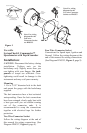
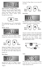
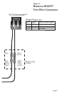
Two Wire Connector Socket
Follow the wiring diagram at the end of
this manual for wiring connections. (See
Diagram HN0357, Figure 4, page 8).
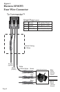
Four Wire Connector Socket
Connections for Speed input, Ignition and
Ground. Follow the wiring diagram at the
end of this manual for wiring connections.
(See Diagram HN0353, Figure 5, page 9).
Used for all splices.
Wires
Heat Shrink Tube
(red or blue)
Metal Butt Connector
(red or blue).
Used for all splices.
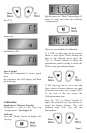
2 wire
Connector
Socket
4 wire
Connector
Socket
4 wire
Connector
2 wire
Connector
Note: For wiring
diagram for the
Two wire Connector
Socket see HN0357.
Note: For wiring
diagram for the
Four wire
Connector Socket
see HN0353.
Page 1
Figure 1