


Bettis P/N 124840E
Revision “B”
Page 16 of 46
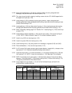
3.2.22 Align hole in guide block (1-30) with the matching holes in the two yoke/guide block
bushings (2-30) and the slots in the arms of yoke (1-70).
NOTE: The yoke pin can be held in place by installing a screw into the .375-16UNC tapped hole in
the upper end of yoke pin (1-80).
3.2.23 Install yoke pin (1-80) by inserting into the upper yoke arm, upper yoke/guide block
bushing, guide block, lower yoke/guide block bushing, lower yoke arm and resting on lower
yoke pin thrust bearing (2-10).
3.2.24 Install guide bar (1-90) into either side of housing (1-10) by inserting through the housing,
through guide block and then insert the guide bar into the other side of housing (1-10).
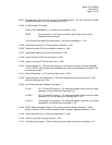
3.2.25 Refer to assembly drawing page 2 of 2 Section A-A. Install spring pin (1-100) into the top
of yoke (1-70).
3.2.26 Install position indicator assembly (1-140) onto the top of yoke (1-70) and over spring pin
(1-100). NOTE: Refer to Section 2 step 2.3.7 for correct installation position.
3.2.27 Install o-ring (2-50) into housing cover (1-20).
3.2.28 Install o-ring seal (2-60) into housing cover (1-20).
3.2.29 Install housing cover (1-20), being careful not to damage o-ring seals (2-50) and (2-60).
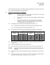
3.2.30 Place lockwashers (1-115) onto hex cap screws (1-110).
NOTE: On G7 through G13 model actuators apply thread adhesive, Locktite 242, to threads of hex
cap screws (1-110). Reference assembly drawing note number 8.
3.2.31 Install hex cap screws (1-110) with lockwashers (1-115) through housing cover (1-20) and
into housing (1-10). NOTE: Leave hex cap screws (1-110) finger tight - do not tighten.
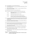
3.2.32 NOTE: Do this step only if groove pins (1-130) have been pulled or if the pins are being
replaced. Drive groove pins (1-130) through housing cover (1-20) and into housing (1-10).
The groove pins should be flush with the cover.
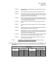
3.2.33 Torque tighten hex cap screws (1-110) until a final lubricated torque, as listed in the
following table, has been achieved.
HOUSING COVER SCREW QUANTITY AND TORQUE TABLE
TORQUE
(±5 % Percent)
TORQUE
(±5 % Percent)
MODEL QTY
FT-lb. N-m
MODEL QTY
FT-LB N-m
G01 4 40 54 G7 8 100 136
G2 6 40 54 G8 12 100 136
G3 8 40 54 G10 16 100 136
G4 8 40 54 G13 20 340 461
G5 8 100 136